3D TERRAIN & GEOTECHNICAL

SETAF2018: Professional 3D Terrain Modeling and Geotechnical Integration Module

Transform complex terrain data into analyzable 3D models in seconds. Combine your AutoCAD data with borehole logs to create a digital twin and cross-section reports for your project.

SETAF 3D Modeling
TBDY 2018 COMPLIANT

SETAF2018 offers a comprehensive module that enables you to model terrain quickly, accurately, and versatilely in geotechnical engineering projects. By combining academic methods (Triangulation, Voronoi, etc.) with software automation, it eliminates manual data entry errors and accelerates your workflow.

SETAF2018's Highlighted 3D Terrain Modeling Features

1. Fully Automatic DXF Data Integration

The software directly recognizes layers in your AutoCAD-based projects. Every file prepared according to the standard table below becomes a 3D model in seconds:

Data TypeLayer NameObject TypeTechnical Function
Terrain BoundariesContourClosed 3D PolylineDefines the outer boundaries and elevations of the model.
Inner PointsInnerPointPointIncreases surface accuracy with detailed points.
BoreholesBoreholePointForms the starting point of the subsurface soil profile.
Foundation ContoursFoundationClosed PolylineDefines the Structure-Soil interaction area.
SETAF2018 Soil Profile Modeling
BOREHOLE INTEGRATION
02

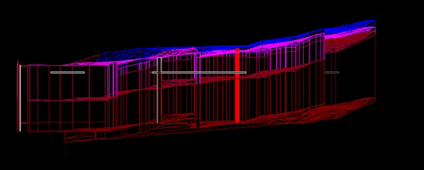
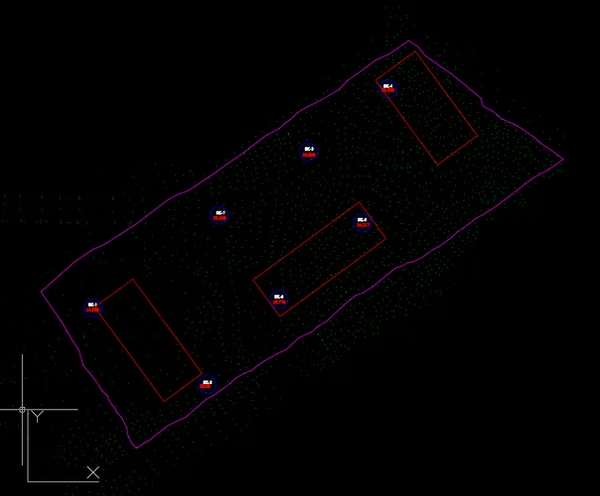
Layered Soil Profile Modeling

Create a true engineering model, not just a surface drawing. When you input borehole data into the system, the software connects the soil layers in harmony with the terrain topography. This feature allows groundwater level and layer changes to be observed in 3D.

  • Dynamic Layer Connections
  • Groundwater Level Analysis
  • Topography-Compliant Cross-Sections

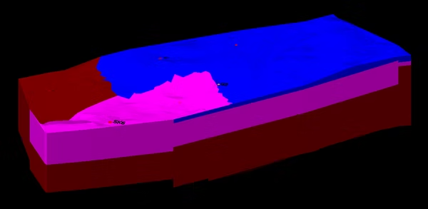
Delaunay Triangulation Engine

At the heart of the software, the triangulation engine creates the most realistic surface form in rugged terrains and steep slopes. This mesh structure allows the model to be exported as DWG and used as volumetric data in other engineering software.

Mathematical algorithm optimized for precise surface formation and seamless data transfer.

Delaunay Triangulation Mesh Structure
DWG EXPORT READY
SETAF2018 Cross-Section Automation Output
🔍 High Precision Output
MODULE RESULTS

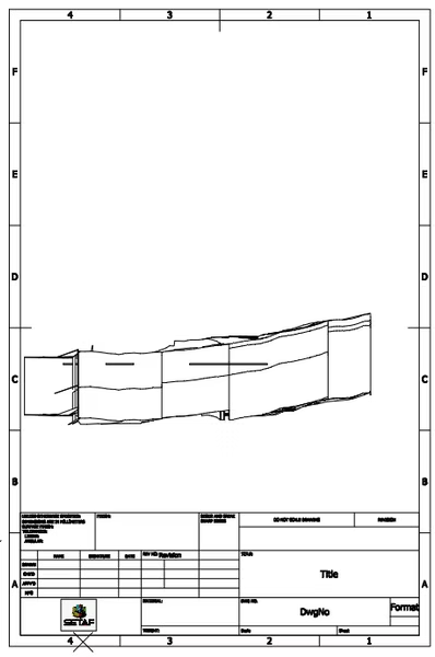
Cross-Section and Perspective Automation

Interactively select any desired line on the model to obtain an instant 2D soil cross-section. Additionally, you can obtain perspective drawings of the model from different angles (front, side, top) and directly include them in your technical reports.

Interactive Selection Automatic drawing with line selection
Perspective View 360° technical angle control
Report Ready Direct technical file format