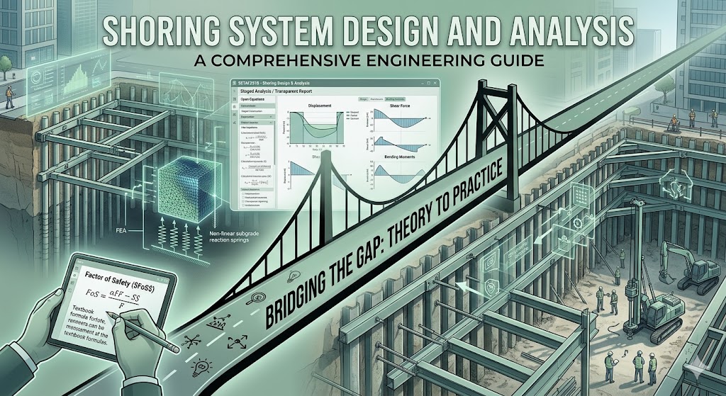
In high-density urban environments, shoring system design and analysis is no longer just about holding back dirt—it is about surgical precision. Whether you are excavating next to a historic building or managing deep groundwater tables, the stability of your excavation is the only thing standing between a successful project and a catastrophic structural failure.
The challenge for modern engineers lies in the transition from abstract soil mechanics to a constructible, safe design. Textbooks provide the formulas, but site constraints—like sensitive utilities and unpredictable surcharge loads—demand a more integrated approach.
This guide explores the critical phases of shoring design, from stability checks to structural component sizing. To bridge the gap between complex theory and daily office efficiency, we will also look at how specialized geotechnical software like SETAF2018 can streamline your workflow, moving you from raw site data to a certified, transparent design report in a fraction of the time.
The Two Pillars of Excavation Shoring
A successful shoring design is composed of two distinct but interdependent systems. Choosing the right combination is critical for both the safety of the site and the project’s bottom line.
1. Earth Retention Systems (The Vertical Support)
The retention system is the actual wall that interfaces with the soil. Depending on the ground conditions and the proximity of adjacent structures, engineers typically choose from:
- Soldier Piles and Lagging: A cost-effective, versatile choice for temporary works where groundwater is not a primary concern. It consists of vertical steel H-piles with horizontal timber or concrete lagging.
- Secant and Tangent Pile Walls: These are formed by intersecting (secant) or touching (tangent) drilled shafts. They offer high stiffness and, in the case of secant walls, an excellent hydraulic barrier for excavations below the water table.
- Diaphragm Walls: Reinforced concrete walls cast in deep trenches. These are the “heavyweights” of shoring, used for the deepest excavations and permanent underground structures.
2. Support Systems (The Lateral Resistance)
While the wall prevents the soil from flowing into the cut, the support system provides the lateral resistance to keep the wall from tilting or sliding.
- Internal Bracing (Struts and Rakers): These transfer the loads from one side of the excavation to the other or down to a base slab. They are ideal when you cannot encroach on neighboring properties.
- External Bracing (Tiebacks and Ground Anchors): These use high-strength steel tendons anchored deep into the stable soil or rock mass behind the wall. Tiebacks provide a clear, open workspace within the excavation, which is a major advantage for construction logistics.
The Physics Behind the Choice
The effectiveness of both these pillars depends entirely on the soil’s shear strength. For instance, the active pressure pushing against your soldier piles and the passive resistance supporting your wall’s embedment depth are direct functions of the [Friction Angle of Soil]. In granular soils, a higher friction angle allows for lower active pressures ($K_a$) and higher passive resistance ($K_p$), significantly reducing the required size of your support members.
Essential Stability Checks in Shoring Design
Designing a shoring system is a game of equilibrium. You are balancing the driving forces (soil and water pressure, surcharges) against the resisting forces (passive pressure, anchor tension, and soil strength). To ensure a safe excavation, every designer must clear three major hurdles.
1. External Stability: The Foundation of Safety
External stability checks treat the shoring wall and the soil mass it supports as a single unit.
- Sliding: Does the wall have enough horizontal resistance to prevent it from being pushed into the excavation?
- Overturning: For cantilever or single-propped walls, is the resisting moment (from embedment) greater than the driving moment from the soil? Typically, a Factor of Safety (FoS) of at least 1.5 is required.
- Bearing Capacity: The vertical component of anchor loads and the wall’s self-weight must be supported by the soil at the base. Excessive bearing stress leads to settlement, which can damage adjacent utilities.
2. Global Stability: Preventing Deep-Seated Failure
Sometimes, the wall itself is perfectly strong, but the entire hillside or soil mass fails along a circular or non-circular slip surface that passes under the wall. This is known as Global Stability or deep-seated failure.
- This check is critical in soft clays or when there are weaker soil layers located below the excavation base.
- Modern standards usually demand an FoS of 1.3 for temporary shoring and 1.5 for permanent works.
3. Basal Heave and Boiling: The Water Factor
When excavating in saturated sands or soft clays, the “bottom” of your excavation can become its weakest point.
- Basal Heave: In soft clays, the weight of the soil outside the excavation can “squeeze” the soil upward at the base of the cut.
- Boiling (Piping): In sandy soils with a high water table, upward seepage pressure can reduce the effective stress to zero, causing the sand to “boil” and the wall to lose all passive support.
In traditional workflows, these checks are often spread across multiple spreadsheets or different software modules. SETAF2018 streamlines this by performing these stability analyses as part of a unified calculation. Because the software understands the relationship between your soil layers and structural elements, you don’t have to manually transfer forces between a “stability” program and a “wall design” program.
Overcoming the “Software Fragmentation” in Shoring Analysis
In most engineering offices, shoring design is a fragmented process. A typical workflow involves calculating earth pressures in a spreadsheet, performing a stability analysis in a geotechnical program, and then manually exporting those reactions into a structural software to design the reinforcement or steel sections.
This “fragmentation” is not just time-consuming; it creates a massive window for data entry errors. SETAF2018 was engineered to eliminate this gap by providing an integrated structural and geotechnical platform.
1. The Subgrade Reaction Method (Non-linear Analysis)
While traditional limit equilibrium methods are great for back-checking, modern shoring requires understanding soil-structure interaction. SETAF utilizes the Subgrade Reaction Method, modeling the soil as a system of non-linear springs. This allows the software to predict wall deflections and bending moments with high precision, reflecting how the soil truly “softens” or “stiffens” under load.
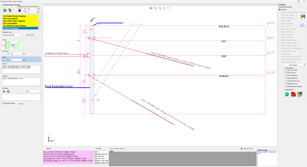
2. Automated Staged Construction: Analysis in a Single Click
In shoring engineering, “Staged Construction” is not just a process—it is the analysis itself. The behavior of the wall, the tension in the anchors, and the soil’s reaction must be calculated for every single foot of excavation.
While many modular geotechnical suites (like Geo5) require you to manually create and manage each stage or even save them as separate files, SETAF2018 automates the entire sequence.
- One-Click Stage Generation: Instead of manually defining each excavation level, SETAF allows you to generate all construction stages automatically. This ensures that the transition from a cantilever state to a fully braced system is handled within a single, cohesive analysis run.
- Integrated Solutions: This automation aligns with our “One Software, Unlimited Solutions” philosophy. Whether you are modeling a simple foundation or a complex multi-layered shoring system, all modules and stages exist within a single file environment.
- Instant Worst-Case Identification: By running all stages simultaneously, the software allows you to visualize displacement, shear force, and moment diagrams across the entire timeline. This ensures that an intermediate stage—which might actually be more critical than the final depth—is never overlooked.
3. Transparent Output: The End of “Black-Box” Engineering
In geotechnical engineering, software output is generally divided into two categories: Analysis Results (displacements, moments, shear forces) and Design Results (structural capacities, reinforcement, anchor checks).
Most industry-standard tools like Plaxis or Geo5 operate as a “black box” in their reporting; they provide results in rigid, table-based formats that hide the underlying logic. SETAF2018 breaks this cycle by offering a dual-layered reporting system that ensures both efficiency and total transparency.
- Global Reports (The Efficiency Layer): For a quick overview, SETAF generates comprehensive global reports. These include analysis data such as wall displacements, section forces (M, V diagrams), and anchor/strut forces in a clean, professional table format.
- Local Reports (The “White-Box” Advantage): This is where SETAF truly stands apart. For design results—such as anchor bond capacity, tendon rupture checks, steel strut structural resistance, and concrete section design—SETAF provides detailed Local Reports.
- Explicit Equations: Unlike the table-based “black-box” outputs of competitors, these reports show every intermediate step. Every formula, design code equation, and calculation process is explicitly displayed.
By moving from the table-only limitations of tools like Geo5 to “White-Box” reporting, SETAF2018 builds immediate trust with peer reviewers and municipal authorities. They don’t just see the final safety factor; they see exactly how you—and the software—arrived at it.
Tired of fragmented workflows and opaque reports? [Try SETAF for Free] – Experience the power of seeing every equation behind your design.
This section helps the reader navigate the practical pros and cons of each system. It’s about choosing the right tool for the job—and the right analysis method for that tool.
Comparing Shoring Wall Types: Which One to Choose?
Selecting the appropriate wall type is a balance between soil conditions, site constraints, and the project’s budget. There is no “one-size-fits-all” solution in shoring system design and analysis, but the following guide covers the most common industry applications:
1. Soldier Piles and Lagging: The Versatile Choice
Soldier piles are the “bread and butter” of temporary shoring. They are best suited for projects where the soil can stand vertically for a short period and where the water table is below the excavation base.
- Best for: Stiff clays, dense sands, and temporary works.
- Analysis Note: While soldier piles are discontinuous systems, they still require rigorous structural verification. SETAF2018 simplifies this by allowing you to define pile spacing and material properties quickly, ensuring that the selected H-beams or pipe piles are structurally optimized for the calculated lateral pressures. By integrating the structural section checks directly within the geotechnical workflow, you can instantly verify if your pile selection meets the required design codes without switching between different software.
2. Secant and Tangent Piles: The Urban Heavyweight
When you are digging deep in a city center next to a sensitive neighbor, stiffness is everything. Secant walls (overlapping piles) provide a rigid, water-tight barrier that minimizes lateral movement.
- Best for: High water tables and urban basement excavations where settlement control is critical.
- Analysis Note: These walls are analyzed as a continuous unit per foot of wall, requiring high-stiffness modeling to predict their impact on adjacent foundations.
3. Diaphragm Walls (Slurry Walls): The Permanent Powerhouse
Diaphragm walls are cast in-situ and often serve as the permanent foundation wall of the building. They offer the highest load-bearing capacity and the best waterproofing performance.
- Best for: Metro stations, deep tunnels, and high-rise building basements.
- Analysis Note: Because they are often permanent, they require a more rigorous long-term analysis, including seismic loading and concrete creep.
Comparing Shoring Wall Types: Which One to Choose?
Selecting the appropriate wall type is a balance between soil conditions, site constraints, and the project’s budget. SETAF2018 is specifically engineered to handle the industry’s most common and technically demanding systems, ensuring that from simple soil nails to complex diaphragm walls, your analysis remains robust.
At-a-Glance Comparison Table: SETAF2018 Capabilities
| Wall Type | Waterproofing | Relative Cost | Stiffness | Common Application | SETAF2018 Status |
| Soil Nailed / Shotcrete | Poor | Low | Low | Slope stability, temporary works | ✅ Available |
| Contiguous Pile | Poor | Moderate | Moderate | Cohesive soils, dry excavations | ✅ Available |
| Tangent Pile | Moderate | High | High | Deep excavations, no gaps | ✅ Available |
| Secant Pile | Excellent | High | High | High water tables, urban sites | ✅ Available |
| Sheet Pile | Good | Moderate | Low/Moderate | Waterfronts, interlocking steel | ✅ Available |
| Diaphragm Wall | Superior | Very High | Very High | Metro boxes, permanent walls | ✅ 3D Alpha / Analysis Pending |
Flexible Support Systems for Every Scenario
Analysis in SETAF2018 isn’t limited to just the wall type; it encompasses the entire mechanical equilibrium of the site. The software allows you to model and analyze the three primary lateral resistance methods used in modern engineering:
- Cantilever Systems: Ideal for shallower cuts where the wall relies entirely on its own stiffness and embedment depth.
- Anchored Systems (Tiebacks): For deep excavations where tension-based stabilization is required. SETAF provides detailed checks for bond length, tendon capacity, and grout-to-soil interaction.
- Strutted Systems (Internal Bracing): Essential for urban sites where you cannot cross property lines with anchors. SETAF handles the compression-based structural checks for steel struts seamlessly.
Strategic Note: While traditional “Soldier Pile and Lagging” systems are not yet part of the SETAF core, our focus remains on providing high-precision analysis for high-stiffness systems (Piles and Diaphragms) and increasingly popular Soil Nail solutions. Furthermore, the introduction of 3D Modeling (Alpha) marks our transition toward an even more integrated geotechnical environment, with 3D analysis modules currently in development.
For those working on standard projects that fall into the “90%” category, using a streamlined tool is often more profitable than a high-end suite. Check out our guide to see how SETAF2018 stacks up against modular competitors like Geo5.
Structural Design of Shoring Elements
In shoring system design and analysis, determining the earth pressure is only half the battle. Once you know the forces acting on the wall, you must transform those pressures into structural dimensions, steel grades, and reinforcement schedules.
A common pitfall in deep excavation projects is the disconnect between the geotechnical model and the structural check. If these two phases are not integrated, a change in soil parameters could invalidate days of structural work.
1. Concrete and Steel Section Checks
Every shoring wall must be checked for bending moments and shear forces.
- Concrete Walls (Secant/Diaphragm): Design involves calculating the longitudinal reinforcement to resist tension and the shear reinforcement (stirrups) to prevent diagonal tension failure.
- Steel Soldier Piles: Design focuses on section modulus and lateral-torsional buckling. The engineer must ensure that the selected H-beam or I-beam can handle the maximum moment derived from the non-linear soil springs.
2. Anchor and Tieback Design
The structural integrity of a restrained system depends on its anchors. This requires calculating:
- The Bond Length: Ensuring the anchor is “glued” into the stable soil mass far enough behind the potential failure plane.
- The Tendon Capacity: Selecting the right number of steel strands to handle the design load.
- Anchor Head & Waler Beam: Designing the steel beams (walers) that distribute the anchor force across multiple piles.
3. The Efficiency Gap: SETAF vs. Heavyweight Suites
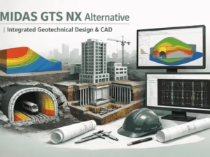
For most engineers, performing these structural checks in high-end finite element software can be a grueling task. In software like Midas (see our guide on [Midas Alternatives]), setting up a simple structural check for a soldier pile often requires complex 3D modeling and manual extraction of nodal forces.
SETAF2018 eliminates this friction. By integrating the structural design codes directly into the geotechnical engine, SETAF allows you to:
- Automatically size reinforcement according to current design codes (e.g., TS500, ACI, or Eurocode).
- Perform steel section checks instantly as the analysis runs.
- Generate a full structural calculation report alongside your geotechnical stability results.
By moving structural checks from “hours” in a separate program to “minutes” within the same platform, you reduce the risk of manual data transfer errors and ensure that your structural members are perfectly optimized for the soil they are retaining.
Common Pitfalls in Shoring Engineering
Even with the most advanced analytical methods, the safety of a shoring system can be compromised by overlooking fundamental engineering realities. Recognizing these common pitfalls is the first step toward a resilient design.
1. Designing with Insufficient Soil Data
One of the most dangerous practices in shoring is “guessing” soil parameters based on a generic description like “stiff clay.” Without site-specific lab tests or reliable field correlations, your design is built on a shaky foundation.
- The Risk: Underestimating the pressure or overestimating the soil’s strength can lead to excessive wall deformation.
- The Solution: Use established correlations to back-check your assumptions. SETAF2018 automates the use of SPT N-value correlations, ensuring that your friction angle and cohesion values are grounded in empirical data rather than guesswork.
2. Underestimating Surcharge Loads from Adjacent Structures
In urban shoring, the soil is rarely the only load. Existing buildings, heavy construction machinery, and traffic on nearby roads exert significant surcharge loads that must be added to the lateral earth pressure.
- The Pitfall: Failing to account for the “Zone of Influence” of an adjacent foundation or a crane platform.
- The Risk: Unexpected structural failure of the wall or damage to neighboring utilities and basements.
- The Solution: Always perform a sensitivity analysis. A robust geotechnical software allows you to model various surcharge scenarios (point, line, or strip loads) to see how they impact the total pressure on your shoring wall.
3. Neglecting “Staged” Drainage and Water Pressure
Water is the engineer’s greatest enemy. Designing for a “dry” state when the groundwater table is high—or failing to account for temporary flooding during a storm—is a recipe for disaster.
- The Pitfall: Assuming static water levels during all stages of excavation.
- The Solution: Use integrated analysis tools that allow you to adjust water tables and pore pressure for every construction stage.
Conclusion: Engineering for Certainty
Shoring system design and analysis is a complex balancing act where geotechnical insights meet structural precision. As we have explored, moving from raw site data to a constructible design requires more than just a set of formulas; it requires a workflow that minimizes error and maximizes transparency.
By integrating stability checks, staged construction analysis, and structural member sizing into a single, transparent platform, SETAF2018 allows you to focus on the engineering decisions that matter.
Frequently Asked Questions About Shoring System Design and Analysis
1. What is the difference between cantilever and restrained shoring systems?
The primary difference lies in how lateral loads are resisted. Cantilever shoring systems rely entirely on the embedment depth (passive resistance) below the excavation line, making them suitable only for shallow cuts or stiff soils. In contrast, restrained shoring systems utilize external supports like ground anchors (tiebacks) or internal bracing (struts and rakers) to handle the higher pressures of deep excavations.
2. How do I determine the factor of safety (FoS) for global stability?
Standard engineering practice typically requires a minimum Factor of Safety of 1.3 for temporary shoring and 1.5 or higher for permanent structures. These values ensure the soil mass is safe against deep-seated rotational failure. SETAF2018 automates these global stability checks, allowing you to verify safety factors across multiple slip surfaces instantly.
3. Why is staged construction analysis necessary in shoring design?
Soil behavior and structural forces are not static; they evolve with every foot of excavation and every anchor pre-tensioning. Often, the maximum bending moment or anchor load occurs during an intermediate stage rather than the final depth. A staged construction analysis allows you to monitor these shifts step-by-step, ensuring that no critical stress state is overlooked during the construction sequence.
4. Can I design soldier pile and lagging walls using SETAF?
While SETAF2018 is not currently designed for soldier pile and lagging systems, it excels in analyzing high-stiffness shoring solutions like contiguous, secant, and tangent pile walls. The software provides a robust environment for these discontinuous systems by allowing engineers to define precise pile diameters and spacing directly within the model. Instead of relying on manual data transfer, the platform integrates structural section checks to instantly verify bending moments and shear capacities for your specific pile layout. This ensures that even the most complex urban excavations are backed by a code-compliant and structurally optimized design. By focusing on these integrated workflows, SETAF2018 empowers engineers to achieve high-precision results with total transparency.