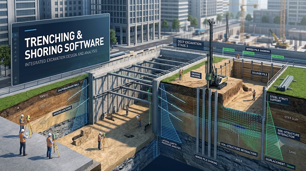
Excavation design becomes more complex the moment the surrounding ground has to remain stable while soil is being removed. What may appear to be a straightforward trench or excavation can quickly become a soil–structure interaction problem involving changing earth pressures, groundwater, surcharge loads, nearby structures, retaining walls, anchors, struts, and multiple construction stages.
This is where trenching and shoring software becomes relevant. Its role is not simply to check whether a retaining wall can resist lateral pressure. Engineers need to understand how the ground and support system behave together as excavation progresses, whether movements remain acceptable, and whether the proposed system satisfies the required stability and structural checks.
The level of analysis naturally depends on the project. A relatively simple trench and a deep, constrained urban excavation do not require identical engineering workflows. This guide explores where that distinction lies, what shoring analysis actually needs to evaluate, and when dedicated software becomes necessary to move from excavation conditions to a safe, buildable shoring design.
What Is Trenching and Shoring Software?
Trenching and shoring software is engineering software used to analyze and design support systems that keep the ground stable during excavation. It brings together the excavation geometry, soil conditions, groundwater, external loads, retaining elements, and construction sequence so engineers can evaluate how the excavation and its support system will behave as work progresses.
This is important because a trench or excavation is not defined by depth and width alone. The same geometry can behave very differently depending on the soil profile, groundwater level, nearby buildings or infrastructure, equipment and other surcharge loads at ground level, and the type of support system being used. In deeper or constrained excavations, these variables can also change from one construction stage to the next.
A complete analysis may therefore need to consider:
- Soil and rock conditions around the excavation
- Groundwater and hydrostatic pressures
- Lateral earth pressures
- Surface surcharge loads
- Nearby structures and infrastructure
- Retaining walls and support elements
- Anchors, soil nails, or internal struts
- Excavation and support installation stages
- Structural forces, stability, and displacement
The purpose of the software is to connect these variables rather than evaluate them independently. A retaining wall that has sufficient structural capacity, for example, does not by itself demonstrate that the excavation system is adequately designed. Ground behavior, wall movement, support forces, stability mechanisms, and the sequence in which excavation and support installation occur can all influence performance.
Modern trenching and shoring software therefore needs to evaluate the excavation as a soil–structure system, rather than treating the retaining wall as an isolated structural element. Dedicated shoring design software can bring these variables into the same engineering workflow, allowing the support system to be evaluated in the context of the ground and the excavation it is intended to stabilize.
Why Trench and Excavation Support Is a Geotechnical Problem
Knowing the depth and geometry of an excavation is not enough to determine how it should be supported. The excavation exists within a soil mass, and removing that soil changes the stress conditions that existed before construction began. The response of the support system therefore depends as much on the ground as it does on the structural elements used to retain it.
A useful way to understand the problem is as a connected sequence:
Ground Conditions → Groundwater → Excavation Sequence → Earth Pressures → Support System → Structural Response → Stability & Displacement
Each part influences what follows. Soil strength, stiffness, and stratigraphy affect the pressures acting on the retaining system. Groundwater introduces hydrostatic pressure and can influence effective stresses and stability. Surcharge loads from nearby buildings, traffic, equipment, or stored materials can further change the demand placed on the excavation support system.
The excavation sequence adds another layer. A deep excavation is not created instantaneously at its final depth. Soil is removed progressively, while anchors, struts, soil nails, or other support elements may be installed at different stages. As the excavation advances, earth pressures, support forces, bending moments, and wall displacements can change with it.
This is why shoring analysis cannot be reduced to a single structural question:
“Can the retaining wall resist the applied load?”
The engineering problem is broader. Engineers also need to ask whether the assumed earth pressures represent the actual ground conditions, how much the wall will move, how anchors or struts will respond, whether the soil mass remains stable, and whether those conditions remain acceptable throughout the excavation sequence.
That makes trench and excavation support fundamentally a soil–structure interaction problem. The retaining wall is important, but it is only one component of a system in which the ground, water, structural supports, external loads, and construction stages continuously interact.
A reliable shoring design therefore needs to evaluate both sides of that system: the geotechnical behavior of the ground and the structural response of the support system.
When Does an Excavation Require an Engineered Shoring System?
Not every excavation requires the same type or level of support. A shallow excavation in competent ground and an urban basement excavation beside an existing building present very different engineering problems. The need for an engineered shoring system depends on the combined effect of excavation geometry, ground conditions, groundwater, surrounding loads, nearby infrastructure, and the way construction will proceed.
There is therefore no universal depth at which every excavation suddenly requires the same shoring solution. Local regulations may establish specific thresholds or mandatory protective measures, but the engineering assessment must still reflect the actual site conditions and applicable design standards.
Excavation Depth
As excavation depth increases, the stresses acting on retaining systems generally become more significant, and the consequences of ground movement can increase as well. Deeper excavations may require retaining walls combined with anchors, struts, or other support elements rather than relying on unsupported or simply sloped excavation faces.
Depth alone, however, should not determine the support strategy. A relatively shallow excavation in difficult ground or beside a sensitive structure may require more careful engineering than a deeper excavation under favorable and unconstrained conditions.
Soil and Rock Conditions
The surrounding ground determines how an excavation is likely to behave once lateral confinement is removed.
Soil stratigraphy, shear strength, stiffness, density, cohesion, friction angle, and the presence of weak or highly variable layers can all influence earth pressures, deformation, and potential failure mechanisms. Rock excavations introduce their own considerations, including discontinuities and weathering.
An engineered shoring design therefore needs a ground model that represents the conditions encountered at the site rather than relying solely on excavation geometry.
Groundwater Conditions
Groundwater can fundamentally change an excavation problem.
Water pressures acting behind a retaining system increase lateral demand, while changes in porewater pressure influence effective stresses within the soil. Depending on the ground and excavation conditions, engineers may also need to consider seepage, hydraulic instability, uplift, or base-heave-related mechanisms.
Groundwater conditions can also change during construction, making them an important consideration when defining excavation stages and temporary works.
Nearby Buildings and Infrastructure
An excavation does not need to collapse for it to cause damage.
Movement of a retaining wall can produce ground deformation outside the excavation, potentially affecting neighboring foundations, roads, utilities, tunnels, or other sensitive infrastructure. In dense urban environments, controlling displacement may therefore be just as important as satisfying ultimate stability requirements.
The closer and more sensitive the surrounding assets are, the stronger the case for a designed support system with explicit deformation and stability checks.
Surcharge Loads
The ground immediately outside an excavation is rarely unloaded.
Construction equipment, material storage, traffic, cranes, temporary facilities, and existing buildings can introduce surcharge loads that increase the lateral pressures acting on the retaining system. Their magnitude, position, and duration can influence wall moments, support forces, and displacement.
These loads should therefore form part of the excavation model rather than being considered separately from the shoring design.
Seismic Conditions
In seismic regions, excavation support systems may also need to account for earthquake-induced changes in lateral earth pressure and structural demand.
The significance of seismic loading depends on the project location, ground conditions, support system, excavation geometry, and applicable regulations. For this reason, seismic effects should be incorporated according to the relevant geotechnical and structural design framework rather than through a universal assumption applied to every excavation.
Construction Sequence
For complex excavations, how the excavation is built can be as important as its final geometry.
Consider a simplified sequence:
Excavate → Install Anchor → Excavate Deeper → Install Second Support → Continue Excavation → Reach Final Level
The retaining system experiences different ground conditions, forces, stiffness, and support configurations at each stage. An analysis performed only at the final excavation depth may therefore fail to represent important conditions that occur during construction.
This is one of the clearest situations in which dedicated excavation shoring software becomes valuable: the engineering model can follow the construction sequence rather than treating the finished excavation as the only condition that matters.
Ultimately, the decision to use an engineered shoring system should be based on risk and site-specific engineering conditions, not depth alone. Regulatory requirements and mandatory excavation-protection rules also vary between countries and jurisdictions, so the applicable local standards must always be checked alongside the engineering analysis.
What Does Trenching and Shoring Software Actually Calculate?
Trenching and shoring software does more than calculate the strength of a retaining wall. Its purpose is to evaluate how soil, groundwater, excavation geometry, external loads, retaining elements, and support systems interact throughout the excavation process.
Depending on the project and analysis method, engineers may need to calculate both the forces acting on the shoring system and the response of the ground and structural elements to those forces.
Lateral Earth Pressures
Excavation removes the lateral support previously provided by the soil mass, creating earth pressures that the retaining system must resist. These pressures depend on factors such as soil properties, groundwater, wall movement, surcharge loads, and excavation geometry.
Classical earth pressure theories such as Rankine and Coulomb provide established frameworks for determining active and passive earth pressures. The appropriate approach and assumptions depend on the retaining system, ground conditions, and design scenario being evaluated.
Wall Bending Moments and Shear Forces
Once lateral pressures and support conditions are established, the retaining wall itself must be analyzed structurally.
Shoring analysis determines the bending moments and shear forces that develop along the wall as excavation progresses. These results influence the structural design of bored piles, diaphragm walls, sheet piles, or other retaining elements and help identify critical sections where demand is greatest.
For staged excavations, the force distribution can change as soil is removed and new support levels are activated.
Horizontal Wall Displacement
A retaining system can remain structurally stable while still moving enough to create problems around the excavation.
Horizontal wall displacement is therefore a critical serviceability consideration, particularly when excavations are located near existing buildings, roads, utilities, or other deformation-sensitive infrastructure.
Shoring software can evaluate how wall movement develops in response to excavation, soil stiffness, support locations, and construction stages. In constrained urban projects, controlling displacement may be one of the governing design requirements rather than simply preventing structural failure.
Anchor and Strut Forces
Anchors and internal struts change how loads are transferred through the shoring system.
The analysis needs to determine the forces developing in these support elements at different excavation stages so that their capacity, spacing, location, and structural components can be evaluated appropriately.
For anchored systems, this can extend beyond calculating tensile force to checks involving tendon capacity, grout-to-ground resistance, and the stability of the supported soil mass. Strut-supported excavations similarly require evaluation of the forces transferred between the retaining walls and internal bracing system.
Overall and Internal Stability
Individual structural elements can satisfy their capacity checks while the excavation system as a whole remains vulnerable to a broader failure mechanism.
Overall stability considers potential failure surfaces involving the surrounding soil mass and support system. Internal stability focuses on failure mechanisms within or directly associated with the supported excavation system, including the interaction between walls, anchors, and retained ground.
These checks are what move shoring design beyond isolated structural member calculations toward evaluation of the excavation as a complete geotechnical system.
Base Heave
The bottom of the excavation is another potential failure zone.
In certain soil conditions, removing overburden can reduce confinement and create conditions in which the excavation base moves upward or becomes unstable. Base heave checks evaluate whether the remaining soil beneath the excavation provides sufficient resistance against this mechanism.
This is particularly relevant for deeper excavations and weaker ground conditions, where stability below the excavation level can become as important as the retaining system along its sides.
Groundwater and Hydrostatic Pressure
Groundwater affects both the forces acting directly on retaining structures and the effective stresses governing soil behavior.
A shoring model may therefore need to account for hydrostatic pressures, groundwater levels on different sides of the retaining wall, and changes in groundwater conditions between construction stages. Depending on the site, groundwater may also introduce additional concerns related to seepage, uplift, or hydraulic stability.
Treating water as part of the ground model rather than as an afterthought is essential for realistic excavation analysis.
Seismic Effects
In seismic regions, excavation support systems may also need to be checked under earthquake loading.
Seismic effects can modify lateral earth pressures and increase demand on retaining walls, anchors, struts, and other support components. Methods such as Mononobe–Okabe can be used in appropriate earth-pressure assessments, while the exact seismic design procedure depends on the applicable code and project conditions.
As with static analysis, the objective is not simply to apply an additional load but to evaluate how that demand affects the entire supported excavation.
Structural ULS and SLS Checks
Ultimately, the calculated forces and movements need to be translated into engineering verification.
Ultimate Limit State (ULS) checks address failure mechanisms and structural capacity, while Serviceability Limit State (SLS) checks consider whether the system performs acceptably under expected conditions—for example, whether wall displacement remains within allowable limits.
Together, these calculations answer two fundamentally different questions:
Will the excavation support system remain safe?
and
Will it behave acceptably while doing so?
This is why effective trenching and shoring software cannot be reduced to an earth-pressure calculator. It needs to connect loading, soil behavior, structural response, stability, and deformation so engineers can evaluate the excavation support system as a whole.
Why Staged Excavation Analysis Matters
A deep excavation does not appear at its final depth instantaneously. It is constructed progressively, and the behavior of the ground and support system changes as soil is removed and new structural elements are introduced.
A simplified construction sequence might look like this:
Stage 1 Excavation → Anchor Installation → Stage 2 Excavation → Second Support Level → Groundwater / Surcharge Changes → Final Excavation Level
At each stage, the retaining system is working under a different set of conditions. Excavation changes the stress state of the surrounding ground. Installing an anchor or strut changes the support conditions of the wall. Further excavation redistributes earth pressures and internal forces again. Groundwater levels, surcharge loads, or temporary construction conditions may also vary between stages.
This means the maximum bending moment, wall displacement, or anchor force does not necessarily occur at the final excavation depth. A critical design condition can develop during an intermediate construction stage and change again as the next support level is installed.
Analyzing only the completed excavation can therefore miss an important part of the engineering problem. The final geometry tells engineers what the excavation eventually becomes; staged excavation analysis considers how the system gets there.
This distinction becomes particularly important for deep excavations supported by multiple anchor levels, struts, sheet piles, bored pile walls, or other systems whose structural behavior evolves with the construction sequence.
Dedicated excavation and shoring design software such as SETAF2018 addresses this by allowing the support system to be analyzed through successive construction stages rather than treating only the final excavation geometry as the design condition. Engineers can evaluate changing excavation levels, support activation, groundwater conditions, and surcharge loads while tracking how forces and displacements develop throughout the project.
For complex shoring projects, staged analysis is therefore not simply a more detailed representation of the final excavation. The construction sequence itself is part of the engineering model.
Common Shoring Systems Used for Trenches and Deep Excavations
There is no single shoring system that is appropriate for every excavation. The choice depends on excavation depth, soil and groundwater conditions, available construction space, nearby structures, allowable movement, construction sequence, and whether the support system is temporary or permanent.
The analysis requirements also change with the system. Some projects are governed primarily by wall behavior, while others depend heavily on anchors, internal bracing, groundwater conditions, or soil–structure interaction.
Bored Pile Walls
Bored pile walls are formed from a series of reinforced concrete piles installed along the excavation perimeter. Depending on pile spacing and configuration, they can provide relatively stiff support for deep excavations and are commonly considered where ground movement must be controlled near buildings or infrastructure.
Analysis needs to consider lateral earth and water pressures, pile bending moments and shear forces, horizontal displacement, embedment, and overall stability. For anchored or braced configurations, the interaction between the pile wall and each support level must also be evaluated as excavation progresses.
Diaphragm Walls
Diaphragm walls are reinforced concrete retaining walls constructed in deep trenches, typically using slurry-supported excavation techniques before reinforcement and concrete placement. Their high stiffness makes them particularly relevant for deep urban excavations, basements, and projects where deformation control and groundwater conditions are major considerations.
Design analysis should evaluate earth and hydrostatic pressures, wall bending and shear, horizontal movement, embedment, support forces, and stability throughout construction. When anchors or internal bracing are introduced at different depths, staged excavation analysis becomes important for understanding how wall response develops before the final excavation level is reached.
Sheet Pile Walls
Sheet pile walls consist of interlocking structural sections driven or installed into the ground to create a continuous retaining barrier. They are widely used for trenches, temporary excavations, waterfront and marine works, and other projects where relatively rapid installation is advantageous.
Engineering analysis typically includes lateral earth and water pressures, section capacity, bending moments, embedment depth, wall displacement, and overall stability. Sheet pile systems may operate as cantilever walls or be supported by anchors and internal struts, making the support configuration and construction sequence important parts of the shoring analysis.
Anchored Shoring Systems
Anchored shoring uses ground anchors to provide lateral support to a retaining wall, allowing deeper excavations to be constructed without filling the excavation with extensive internal bracing. Multiple anchor levels may be installed progressively as excavation advances.
The design must consider more than the tensile force in the anchor. Engineers may need to evaluate anchor loads, tendon capacity, bond or pullout resistance, anchor geometry, wall forces and displacement, and internal and overall stability. Because each anchor becomes active at a particular construction stage, its installation sequence also influences the behavior of the complete excavation support system.
Soil-Nailed Systems
Soil-nailed systems reinforce the retained ground by installing closely spaced reinforcing elements as excavation proceeds, typically combined with a facing such as shotcrete. Unlike conventional anchored walls, the reinforced soil mass itself becomes an important component of the retaining mechanism.
Analysis should consider nail forces and resistance, facing behavior, pullout capacity, internal stability, overall stability, and deformation of the reinforced ground. Because soil nails are normally installed progressively from the top downward, the excavation sequence and changing geometry should also be represented when evaluating system performance.
Internally Braced / Strut-Supported Systems
Internally braced excavations use structural members—commonly horizontal steel struts and walers—to transfer lateral loads between opposing retaining walls or other support points. They are particularly useful where property boundaries, surrounding structures, or other site constraints make external ground anchors impractical.
Analysis needs to determine strut forces, wall bending moments, shear forces, displacement, connection demands, and system stability at each relevant stage. Installing or removing struts changes the structural boundary conditions of the excavation, so the timing and sequence of support activation are integral to the analysis rather than merely construction details.
These systems solve the same broad problem—maintaining a safe excavation—but they do so through different load-transfer mechanisms. Effective trenching and shoring software therefore needs enough flexibility to represent the retaining wall, ground conditions, support elements, and construction sequence appropriate to the system being designed.
Trenching vs. Deep Excavation: Do They Require the Same Analysis?
Trenching and deep excavation belong to the same broad family of excavation-support problems, but they should not be treated as interchangeable engineering conditions. A trench is typically characterized by its relatively narrow geometry and may require anything from a straightforward protective system to a fully engineered shoring design. A deep or highly constrained excavation, by contrast, often involves multiple interacting support levels, stricter displacement requirements, and more complex soil–structure behavior.
The important distinction is therefore not simply trench versus excavation, or shallow versus deep. Analysis requirements should reflect the ground conditions, groundwater, excavation geometry, surrounding environment, support system, and consequences of movement.
| Engineering Consideration | Typical Trench | Deep / Constrained Excavation |
| Geometry | Often relatively narrow | Project-specific and potentially large or irregular |
| Support complexity | Can be relatively simple | Often multi-level or multi-component |
| Ground interaction | Important | Frequently a governing design consideration |
| Anchors / struts | Project-dependent | Frequently required |
| Staged analysis | Depends on depth, support system, and construction sequence | Often significant to understanding system behavior |
| Displacement control | Context-dependent | Often critical, particularly in urban environments |
| Adjacent structures | May be limited | Frequently a major design constraint |
A trench in favorable ground with limited surrounding constraints may not require the same analytical depth as a multi-level basement excavation beside existing foundations. But the word trench itself does not imply that the engineering problem is simple. A trench can still involve weak soils, high groundwater, significant surcharge loads, nearby utilities, traffic, or support systems whose behavior changes as excavation proceeds.
The opposite is also important. Deep excavation analysis is not simply trench analysis performed at a greater depth. As excavations become deeper or more constrained, wall stiffness, anchor or strut activation, construction stages, ground movement, and the response of neighboring structures become increasingly interconnected. The design may be governed not only by ultimate stability but also by how much the retaining system and surrounding ground are allowed to move.
This is why the scope of trenching and shoring software can overlap with dedicated deep excavation design tools without the two terms meaning exactly the same thing. Both address excavation support, but the required level of modeling should increase with the complexity and risk of the engineering problem.
For deep and constrained projects in particular, dedicated excavation shoring software needs to move beyond basic earth-pressure and wall-capacity checks toward staged soil–structure analysis, support-system design, stability verification, and displacement assessment.
Why Shoring Design Goes Beyond Analysis
A safe analysis result is not the final project deliverable. Calculating lateral earth pressures, wall displacement, bending moments, anchor forces, or a factor of safety establishes whether the proposed system performs under the analyzed conditions. The engineering workflow still has to turn those results into a design that can be documented, reviewed, quantified, and ultimately constructed.
For an excavation support project, that workflow typically continues through:
Ground Data → Excavation Model → Analysis → Shoring Design → Structural Checks → Drawings → Quantity Takeoff → Report
These stages are closely connected. Ground conditions and groundwater influence the excavation model; the excavation sequence determines how loads and support conditions develop; analysis results inform wall sections, reinforcement, anchors, nails, or struts; and those design decisions must then remain consistent across drawings, quantities, and calculation reports.
This is where relying on several disconnected engineering tools can create unnecessary work. If analysis results are manually transferred into structural calculations, reconstructed in CAD, copied into quantity spreadsheets, and finally assembled into a report, every transition becomes another point that must be checked when the design changes.
For that reason, the value of shoring design software should not be measured only by the analyses it can perform. For firms responsible for complete excavation support projects, an equally important question is how far the software can carry the engineering work after the analysis is complete.
How SETAF2018 Supports the Complete Excavation and Shoring Workflow
SETAF2018 is designed as an all-in-one geotechnical environment for excavation and shoring projects, connecting the ground model and staged excavation analysis with the design and documentation tasks that follow.
Its workflow can be summarized as:
Soil & Groundwater Data
→ Staged Excavation
→ Wall + Anchor / Soil Nail / Strut Modeling
→ Shoring Analysis
→ ULS / SLS & Stability Checks
→ Structural Design
→ DWG Drawings
→ Quantity Takeoff
→ Engineering Report
This means an engineer can begin with the conditions governing the excavation, evaluate how the retaining and support system behaves through successive construction stages, perform the required structural and stability checks, and then carry the resulting design into project documentation.
The advantage is not simply having more features in one program. It is maintaining a more continuous relationship between what was modeled, what was calculated, what was designed, and what is ultimately delivered.
For engineering offices handling deep excavations, anchored systems, bored pile walls, sheet piles, soil-nailed structures, or internally braced excavations, this reduces the need to rebuild the same project across separate analysis, CAD, quantity, and reporting environments.
Explore how SETAF2018’s excavation and shoring design software capabilities bring these stages together within a single project workflow.
Frequently Asked Questions About Trenching and Shoring Software
What is trenching and shoring software?
Trenching and shoring software is engineering software used to analyze and design support systems for trenches, deep excavations, basements, and other below-ground construction. It can account for soil conditions, groundwater, earth pressures, surcharge loads, retaining walls, anchors, struts, and construction stages. More advanced platforms also evaluate structural forces, displacement, and stability rather than treating the retaining wall as an isolated element.
What is the difference between trenching and shoring?
Trenching refers to creating a relatively narrow excavation in the ground, while shoring refers to the support system used to stabilize the excavation and surrounding ground where support is required. Shoring may involve sheet piles, bored pile walls, anchors, soil nails, struts, or other retaining systems. Not every trench presents the same engineering conditions, so the required support and level of analysis depend on depth, ground conditions, groundwater, surrounding structures, loads, and applicable regulations.
What software is used for shoring design?
Dedicated shoring design software is used when engineers need to evaluate the interaction between the ground, excavation, retaining wall, and support elements rather than performing only a structural wall calculation. SETAF2018, for example, combines staged excavation analysis with bored pile, diaphragm wall, sheet pile, anchor, soil nail, and strut-supported system modeling. It also extends the workflow into structural checks, design, drawings, quantity takeoff, and reporting.
How is shoring for a deep excavation analyzed?
Deep excavation shoring is analyzed by modeling the ground conditions, groundwater, excavation geometry, surcharge loads, retaining system, and support elements. Engineers then evaluate earth pressures, wall forces and displacement, anchor or strut forces, and relevant internal and overall stability conditions. For multi-stage excavations, these responses should be assessed as excavation and support installation progress rather than considering only the final excavation depth.
Why is staged excavation analysis important?
Staged excavation analysis matters because the forces acting on a shoring system change during construction. Excavating to a new level, installing an anchor or strut, changing groundwater conditions, or introducing another support level can redistribute earth pressures, bending moments, support forces, and wall displacement. A critical condition may therefore occur during an intermediate stage rather than at the final excavation depth. The construction sequence itself becomes part of the engineering model.
Can shoring software calculate anchors and struts?
Yes, provided the software supports anchored and internally braced excavation systems. Depending on the platform, analysis can determine the forces developing in anchors and struts as the excavation progresses and support levels become active. More complete workflows may also include anchor capacity and pullout checks, structural verification, wall-support interaction, and stability assessments rather than reporting support forces alone.
Can the same software analyze sheet piles and bored pile walls?
Yes. An integrated excavation support platform can support multiple retaining systems within the same shoring analysis environment. SETAF2018 includes both sheet pile and bored pile wall systems alongside diaphragm walls, anchors, soil nails, and steel struts. This is particularly useful for engineering firms working across different excavation types because the underlying workflow—from ground conditions and staged analysis to design and project documentation—can remain consistent even when the selected retaining system changes.