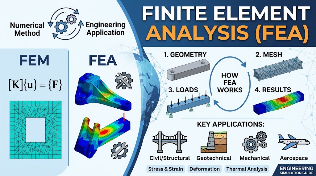
Finite element analysis (FEA) is a numerical engineering technique used to predict how a structure, component, or physical system will behave under specific loads and boundary conditions. It works by dividing a complex model into smaller regions called finite elements, solving the governing equations for each element, and combining those results to estimate the behavior of the complete system.
Engineers use finite element analysis to evaluate factors such as stress, strain, displacement, deformation, temperature, and structural response before a design is built or implemented in the real world. This makes FEA particularly useful when geometry, loading conditions, or material behavior are too complex for simplified analytical calculations.
FEA is based on the Finite Element Method (FEM), but the two terms are not exactly identical. FEM refers to the underlying numerical method, while FEA refers to applying that method to solve and interpret practical engineering problems.
What Does FEA Stand For?
FEA stands for Finite Element Analysis, an engineering analysis process used to evaluate how a structure or physical system responds to defined loads, constraints, and other conditions. It is based on the Finite Element Method (FEM), the numerical method used to divide a complex problem into smaller, solvable elements.
Although FEA and FEM are often used interchangeably, they describe different parts of the process:
| Term | Meaning |
| FEA — Finite Element Analysis | The engineering analysis performed using the finite element method to predict and interpret the behavior of a system. |
| FEM — Finite Element Method | The underlying numerical method used to discretize a continuous physical problem into smaller finite elements and solve the governing equations. |
| Finite Element Model | The computational representation of the problem, including its geometry, mesh, elements, nodes, material properties, loads, and boundary conditions. |
In simple terms, FEM is the numerical method, FEA is the engineering application of that method, and the finite element model is the digital representation on which the analysis is performed.
How Does Finite Element Analysis Work?
Rather than attempting to solve a complex physical system with a single equation, finite element analysis divides the problem into thousands—or even millions—of smaller, manageable pieces called finite elements. The behavior of each element is calculated individually using numerical methods, and these local solutions are then assembled to predict the behavior of the complete structure.
Whether engineers are analyzing a bridge component, a retaining wall, a mechanical part, or a soil mass, the overall workflow follows the same fundamental process.
1. Define the Geometry
The first step is creating the physical model to be analyzed. Depending on the application, this may be a two-dimensional (2D) or three-dimensional (3D) representation of the structure or system.
The geometry can represent almost any engineering object, including a foundation, retaining wall, bridge component, machine part, pressure vessel, or an entire soil domain. The accuracy of this model is important because it defines the physical boundaries on which the analysis will be performed.
2. Define Material Properties
Once the geometry has been created, engineers assign the material properties that describe how each part behaves under loading.
Depending on the analysis, these properties may include Young’s modulus, Poisson’s ratio, density, strength, stiffness, thermal properties, or geotechnical soil parameters. More advanced analyses may also require selecting an appropriate constitutive model to represent nonlinear material behavior.
The quality of an FEA model depends heavily on whether the selected material model accurately represents real-world physical behavior. Even a highly refined numerical model cannot produce reliable results if the input material properties are unrealistic.
3. Apply Loads and Boundary Conditions
The next step is defining the conditions that the model will experience during operation.
Typical loading conditions include external forces, pressure, gravity, temperature changes, displacement constraints, and dynamic or seismic effects. Boundary conditions specify how the model is supported or restrained, allowing the solver to simulate realistic operating conditions.
In geotechnical engineering, boundary conditions may also represent soil confinement, groundwater conditions, surcharge loads, structural supports, or soil–structure interaction. Properly defining these conditions is often just as important as creating the geometry itself.
4. Create the Finite Element Mesh
After the model has been prepared, it is divided into a network called a mesh.
The mesh consists of many small finite elements connected by nodes, where the unknown variables are calculated. Each node contains one or more degrees of freedom, such as displacement or rotation, depending on the analysis type.
In simple terms, the process follows this sequence:
Complex geometry → Mesh → Finite elements → Nodes → Degrees of freedom
A finer mesh generally improves the ability to represent complex geometries and stress gradients, but it also increases computational cost. Engineers therefore aim to create a mesh that provides sufficient accuracy without making the analysis unnecessarily expensive.
5. Solve the System of Equations
Once the model has been fully defined, the solver performs the numerical calculations.
Behind the interface, the solver assembles the equations associated with individual elements into a global system of equations representing the entire model. These governing equations are solved simultaneously while satisfying equilibrium, material behavior, loads, and boundary conditions.
Instead of finding an exact analytical solution to complex differential equations, FEA uses numerical approximations to produce practical engineering results that closely represent real-world behavior.
6. Interpret the Results
The final stage is interpreting the numerical results and converting them into engineering decisions.
Depending on the analysis, FEA may predict stresses, strains, displacements, deformation, internal forces, temperature distribution, vibration characteristics, or pore pressure. Engineers review these results to identify critical regions, evaluate safety, verify design assumptions, and optimize the model before construction or manufacturing.
In geotechnical applications, engineers commonly evaluate wall displacement, bending moments, earth pressures, settlement, structural forces, and soil response to assess the performance of foundations, retaining systems, and excavation support structures.
What Are Elements, Nodes and Meshes in FEA?
Finite element analysis relies on three closely related concepts: elements, nodes, and the mesh. Together, they transform a continuous physical structure into a numerical model that can be solved by a computer. Understanding these building blocks makes it much easier to understand how FEA predicts the behavior of complex engineering systems.
Finite Elements
Finite elements are the small computational regions into which a physical model is divided. Instead of solving an entire structure as one highly complex problem, FEA breaks it into many simpler elements that can each be analyzed individually.
Depending on the application and geometry, elements can be one-, two-, or three-dimensional:
- 1D elements are commonly used for beams, trusses, piles, and structural members.
- 2D elements are used for plane stress, plane strain, shells, and thin structural components.
- 3D elements are used for solid bodies with complex three-dimensional stress distributions.
Each element represents only a small portion of the overall structure, but when thousands or even millions of elements are combined, they can accurately approximate the behavior of the complete system.
Nodes
Nodes are the connection points between finite elements. They define the geometry of each element and are the locations where the solver calculates the unknown variables during the analysis.
Each node contains one or more degrees of freedom (DOFs), which represent the possible ways that point can respond to loading. Depending on the analysis type, these may include translational displacement, rotational movement, temperature, pressure, or other field variables.
Because adjacent elements share common nodes, the solver can assemble the local behavior of individual elements into a continuous representation of the entire structure.
Mesh
A mesh is the complete network of finite elements and nodes covering the entire analysis domain. The process of generating this network is known as meshing, and it is one of the most important stages of any finite element analysis.
The mesh determines how accurately the geometry and its physical behavior can be represented. Smaller elements generally capture stress concentrations, curved surfaces, and complex geometries more accurately, while larger elements reduce computational time.
However, a finer mesh does not automatically produce a better engineering model. Mesh quality is only one factor affecting solution accuracy. If the material properties, constitutive models, loads, or boundary conditions do not realistically represent the physical problem, refining the mesh alone cannot produce reliable results. Effective FEA depends on the combination of an appropriate mesh, realistic engineering assumptions, and accurate input data.
Common Types of Finite Elements
Finite element analysis can use different types of elements depending on the geometry being modeled, the expected physical behavior, and the required level of accuracy. Selecting the appropriate element type is an important part of building an efficient and reliable engineering model. More advanced element types are not necessarily better—the best choice depends on the problem being solved.
1D Beam or Bar Elements
One-dimensional (1D) beam and bar elements are commonly used to model long, slender structural members where one dimension is significantly larger than the others. Instead of representing the full three-dimensional geometry, these elements simplify the member into its centerline while accurately capturing its structural behavior.
Typical applications include:
- Beams and frames
- Piles and micropiles
- Structural supports
- Anchors and tie rods
- Other line-based structural members
Because they require significantly fewer computational resources than solid elements, beam elements are widely used in structural and geotechnical engineering where slender members dominate the model.
2D Elements
Two-dimensional (2D) elements are used when the physical behavior can be represented on a cross-section without explicitly modeling the full three-dimensional geometry.
Common 2D formulations include:
- Plane stress for thin structural components
- Plane strain for long structures with uniform cross-sections
- Axisymmetric models for rotationally symmetric geometries
These elements are frequently applied in civil and geotechnical engineering to analyze retaining walls, embankments, tunnels, foundations, soil profiles, and excavation support systems while maintaining an efficient computational model.
Shell Elements
Shell elements combine the characteristics of plate and membrane behavior, making them suitable for thin structures where one dimension (thickness) is much smaller than the other two.
Typical applications include:
- Steel plates
- Concrete slabs
- Thin retaining structures
- Pressure vessels
- Storage tanks
- Aircraft and automotive body panels
Shell elements efficiently capture both in-plane and bending behavior without requiring a full three-dimensional solid mesh, making them well suited for lightweight structural systems.
3D Solid Elements
Three-dimensional solid elements provide the most complete geometric representation of a structure by modeling its full volume. They are typically used when stresses vary significantly throughout the thickness or when complex three-dimensional interactions cannot be simplified using beam, shell, or 2D elements.
Solid elements are commonly applied to:
- Complex machine components
- Massive concrete structures
- Foundation blocks
- Mechanical assemblies
- Components with irregular geometry
- Advanced soil–structure interaction models
Although solid elements can produce highly detailed results, they also require greater computational effort and more detailed input data.
The most sophisticated element type is not automatically the most appropriate one. Experienced engineers select element types based on the engineering problem, expected structural behavior, available material data, and the level of accuracy required. In many practical applications, a well-designed beam or 2D model can provide results that are both accurate and computationally efficient, while unnecessarily complex models may increase analysis time without improving engineering decisions.
FEA vs. FEM: What Is the Difference?
Although Finite Element Method (FEM) and Finite Element Analysis (FEA) are frequently used as interchangeable terms, they describe different aspects of the same engineering process.
FEM is the mathematical and numerical method used to solve complex physical problems by discretizing a continuous domain into smaller finite elements. FEA, on the other hand, is the practical engineering application of that method to evaluate the behavior of real-world structures, components, and systems under specific loading conditions.
| FEM | FEA | |
| Full name | Finite Element Method | Finite Element Analysis |
| Meaning | Numerical calculation method | Engineering application of FEM |
| Focus | Mathematical formulation | Physical engineering problem |
| Input | Governing equations | Geometry, materials, loads, boundary conditions |
| Output | Numerical solution | Engineering interpretation and design insights |
The relationship can be viewed as a simple workflow:
FEM (the numerical method) → Finite element model → FEA (the engineering analysis) → Engineering decisions
In everyday engineering practice, FEM and FEA are often used interchangeably, although FEM technically refers to the numerical method, while FEA refers to the engineering analysis performed using that method. Understanding this distinction helps clarify technical discussions, software capabilities, and engineering workflows.
What Types of Finite Element Analysis Are There?
Finite element analysis can be applied to many different engineering problems, from evaluating the strength of a bridge to predicting the thermal behavior of electronic components or the deformation of soil surrounding an excavation. The type of FEA performed depends on the physical behavior being investigated and the engineering questions that need to be answered.
Linear Static Analysis
Linear static analysis is the most common type of finite element analysis and is typically used when loads remain constant and structural deformations are relatively small. The analysis assumes that the relationship between load and displacement is linear and that the material behaves elastically throughout the simulation.
This approach is widely used for evaluating stresses, strains, displacements, and support reactions in structures operating under normal service conditions. Because of its computational efficiency, it often serves as the starting point for many engineering design studies.
Nonlinear Analysis
Many real engineering problems cannot be accurately represented using linear assumptions. Nonlinear analysis accounts for changes in material behavior, structural geometry, or contact conditions that occur during loading.
The three most common sources of nonlinearity are:
- Material nonlinearity, where materials no longer follow a linear stress-strain relationship, such as plastic deformation, cracking, or nonlinear soil behavior.
- Geometric nonlinearity, where large displacements or rotations significantly alter the structural response during loading.
- Contact nonlinearity, where components come into contact, separate, or slide against one another during the analysis.
Nonlinear analysis is particularly important when modeling complex structural behavior or geotechnical systems, where soil often exhibits nonlinear stress-strain characteristics under changing loading conditions.
Dynamic Analysis
Dynamic analysis evaluates structures subjected to loads that vary over time. Unlike static analysis, it considers inertia and damping effects to predict how a structure responds to transient or continuously changing forces.
Typical applications include earthquake engineering, machinery vibration, impact loading, moving vehicles, blast loads, and other time-dependent structural problems.
Modal Analysis
Modal analysis determines the natural frequencies and mode shapes of a structure. Every structure has characteristic vibration frequencies, and if external excitation matches one of these frequencies, resonance may occur.
Engineers perform modal analysis to understand vibration behavior, improve structural performance, and reduce the risk of excessive oscillation or fatigue in buildings, bridges, machinery, vehicles, and industrial equipment.
Thermal Analysis
Thermal analysis predicts how heat moves through a material or structure and how temperature changes affect engineering performance.
Typical outputs include temperature distribution, heat flux, thermal gradients, and thermally induced stresses. These analyses are commonly used in mechanical engineering, electronics cooling, manufacturing processes, and infrastructure exposed to significant temperature variations.
Coupled Analysis
Many engineering problems involve multiple physical phenomena acting simultaneously. Coupled analysis combines two or more disciplines within a single simulation to capture their interaction more accurately.
Examples include:
- Soil–groundwater interaction in geotechnical engineering
- Thermal–structural analysis, where temperature changes influence structural behavior
- Fluid–structure interaction (FSI), where flowing fluids interact with deformable structures
By considering these interacting physical processes together, coupled analyses often provide a more realistic representation of complex engineering systems than isolated single-physics simulations.
What Is Finite Element Analysis Used For?
Finite element analysis is used across many engineering disciplines to predict how structures, materials, and physical systems respond to real-world conditions before they are built or modified. By replacing many physical prototypes with virtual simulations, FEA helps engineers improve safety, optimize designs, reduce development costs, and better understand structural behavior under a wide range of loading conditions.
Structural and Civil Engineering
In structural and civil engineering, FEA is widely used to evaluate the performance of buildings, bridges, tunnels, foundations, and retaining structures before construction begins.
Engineers use finite element analysis to estimate stresses, deformations, internal forces, and structural stability under various loading scenarios, including dead loads, live loads, wind, seismic forces, and temperature effects. These simulations support safer and more efficient structural designs while helping identify critical areas that may require reinforcement or redesign.
Geotechnical Engineering
Finite element analysis is also an important tool in geotechnical engineering, particularly for problems involving complex soil behavior and soil–structure interaction.
Typical applications include:
- Excavation support systems
- Retaining walls
- Tunnel construction
- Foundation behavior
- Settlement analysis
- Soil–structure interaction
- Slope stability
- Groundwater-coupled analyses
In these applications, FEA can model interactions between soil, groundwater, and structural components that are often difficult to represent using simplified analytical equations alone. This makes it valuable for evaluating staged construction, complex excavation sequences, nonlinear soil behavior, and deformation-sensitive projects.
However, not every geotechnical engineering problem requires finite element analysis. Many routine engineering tasks—such as bearing capacity calculations, conventional settlement assessments, slope stability evaluations, or code-based foundation design—can often be solved efficiently using established analytical or limit equilibrium methods. The appropriate analysis method should always be selected according to the engineering problem, the required level of accuracy, available site investigation data, and applicable design standards rather than assuming that a more complex numerical model will always produce a better engineering solution.
Mechanical Engineering
Mechanical engineers use FEA to predict how individual components and assemblies respond to operational loads throughout their service life.
Typical analyses include stress distribution, deformation, fatigue assessment, contact behavior, and failure prediction. FEA enables engineers to identify weak points, optimize component geometry, reduce material usage, and improve product reliability before manufacturing begins.
Automotive and Aerospace Engineering
The automotive and aerospace industries rely heavily on finite element analysis throughout the design process because physical testing alone would be prohibitively expensive and time-consuming.
Common applications include crashworthiness studies, vibration analysis, thermal loading, fatigue evaluation, structural optimization, lightweight design, and certification support. Engineers can evaluate hundreds of design iterations digitally before selecting prototypes for physical validation.
Energy and Industrial Engineering
FEA is extensively used in energy production and industrial facilities where structures operate under demanding mechanical and thermal conditions.
Typical applications include pressure vessels, pipelines, rotating equipment, turbines, offshore structures, storage tanks, and energy infrastructure. Engineers use simulation to evaluate structural integrity, thermal stresses, vibration behavior, and long-term operational performance, helping improve reliability while reducing maintenance costs and operational risks.
How Is Finite Element Analysis Used in Geotechnical Engineering?
Geotechnical finite element analysis differs from many conventional structural analyses because engineers are not only modeling structural components but also the behavior of soil, groundwater, and soil–structure interaction. Unlike steel or concrete, soil is a natural material whose properties vary with depth, moisture, stress history, and loading conditions, making many geotechnical problems inherently more complex.
At the same time, it is important to recognize that finite element analysis is only one of several engineering approaches available for geotechnical design. Depending on the project objectives, engineers may combine finite element methods with established analytical or limit equilibrium methods to obtain efficient and reliable design solutions.
Excavation Support Structures
Excavation support systems are among the most common applications of numerical analysis in geotechnical engineering. During excavation, engineers must evaluate not only the structural capacity of the retaining system but also how the surrounding soil responds as construction progresses.
Numerical models are commonly used to predict:
- Wall deformation
- Bending moments
- Anchor forces
- Earth pressures
- Support reactions
These results help engineers optimize retaining wall layouts, evaluate staged excavation sequences, verify structural performance, and control ground movements that may affect nearby buildings or infrastructure.
Foundation Analysis
Foundation analysis focuses on understanding how structural loads are transferred into the ground and how the supporting soil responds over time.
Typical engineering evaluations include:
- Settlement
- Bearing behavior
- Stress distribution
- Pile or rigid inclusion performance
- Soil–foundation interaction
While finite element analysis can model complex foundation systems and interaction effects, many practical foundation designs continue to rely on well-established geotechnical engineering methods. Depending on the design objective, engineers may use analytical stress distribution methods such as Boussinesq or Mindlin–Geddes solutions, together with consolidation approaches based on Terzaghi’s one-dimensional consolidation theory, to evaluate settlement and bearing performance. These methods remain widely accepted because they provide efficient, code-supported solutions for many routine foundation engineering problems while maintaining a high level of engineering reliability. SETAF2018 incorporates these established approaches as part of its foundation analysis workflow.
Slope Stability
Slope stability provides another good example of why finite element analysis is not the only numerical technique available in geotechnical engineering.
In professional practice, slope stability is commonly evaluated using one of two approaches:
- Limit Equilibrium Method (LEM)
- Finite Element Method (FEM), often through strength reduction techniques
Both approaches aim to evaluate slope safety, but they answer the problem in different ways. Limit equilibrium methods calculate the balance between driving and resisting forces along potential failure surfaces, while finite element approaches estimate failure through the stress–strain response of the soil mass.
For many routine engineering projects, the Limit Equilibrium Method remains the industry-standard approach because it provides reliable safety factor calculations with efficient computational effort. SETAF2018 follows this established methodology by performing slope stability analyses using limit equilibrium methods to determine critical slip surfaces and calculate the corresponding factors of safety.
The choice between FEM-based slope analysis and limit equilibrium methods ultimately depends on the engineering problem, the complexity of soil behavior, the available site investigation data, and the level of detail required for the design. In many projects, these approaches are complementary rather than competing, with engineers selecting the method that best matches the project’s objectives.
Does Every Geotechnical Problem Require Finite Element Analysis?
No. While finite element analysis is one of the most powerful numerical tools available to engineers, it is not always the most appropriate solution for every geotechnical engineering problem.
The purpose of engineering analysis is not to use the most sophisticated calculation method possible—it is to select the method that provides the appropriate balance between accuracy, efficiency, available site data, and project requirements. For many routine design tasks, well-established analytical and semi-empirical methods remain reliable, computationally efficient, and fully consistent with engineering standards.
In practice, experienced geotechnical engineers choose the analysis method based on the complexity of the problem rather than assuming that every project requires a full finite element model.
FEA May Be Appropriate When…
Finite element analysis becomes particularly valuable when the engineering problem involves behavior that cannot be adequately represented using simplified analytical approaches.
Typical situations include:
- Complex geometry that cannot be simplified using conventional engineering assumptions
- Significant soil–structure interaction between foundations, retaining systems, and surrounding ground
- Nonlinear material behavior where soil properties change as loading progresses
- Staged construction sequences, such as deep excavations or tunnel excavation
- Advanced deformation analysis where displacement predictions are critical
- Coupled problems involving multiple physical processes, such as groundwater and structural interaction
In these situations, FEA provides engineers with a detailed understanding of stress distribution, deformation patterns, and interaction effects that would be difficult to obtain using traditional calculation methods.
Classical or Specialized Engineering Methods May Be More Efficient When…
Many everyday geotechnical engineering problems do not require the computational complexity of finite element analysis.
Established engineering methods are often better suited for:
- Standard foundation design
- Preliminary engineering studies
- Code-based design verification
- Conventional settlement estimation
- Bearing capacity calculations
- Routine liquefaction evaluation
- Many slope stability assessments using the Limit Equilibrium Method
These approaches have been validated through decades of engineering practice and remain the preferred solution for many design scenarios because they are efficient, transparent, and directly aligned with widely adopted engineering standards.
Rather than replacing these methods, finite element analysis complements them by addressing problems that require a higher level of numerical detail.
The best engineering solution is not necessarily the one that uses the most advanced numerical model—it is the one that uses the most appropriate method for the problem being solved.
This is why many modern geotechnical engineering platforms combine classical analytical methods, specialized geotechnical calculations, and numerical analysis within a single workflow instead of relying exclusively on finite element analysis. Engineers can then select the level of analysis that best matches the project objectives, available investigation data, required design accuracy, and applicable standards. This problem-driven approach often leads to more efficient engineering decisions than applying the same numerical method to every project.
FEA vs. Classical Geotechnical Analysis Methods
Finite element analysis is an extremely powerful engineering tool, but it is not intended to replace every traditional geotechnical calculation. In practice, engineers choose the analysis method based on the complexity of the project, the available investigation data, applicable design standards, and the level of detail required for decision-making.
For many routine projects, classical analytical methods provide accurate, transparent, and computationally efficient solutions. For more complex problems involving nonlinear behavior or significant soil–structure interaction, finite element analysis may offer additional insight that simplified methods cannot capture.
| FEA | Classical / Analytical Methods | |
| Model complexity | High | Low–Medium |
| Geometry | Complex | Standardized |
| Soil behavior | Advanced constitutive models possible | Simplified engineering assumptions |
| Computation | Higher | Lower |
| Input requirements | Extensive | More limited |
| Interpretation | Requires specialist knowledge | Familiar engineering workflow |
| Preliminary design | Sometimes excessive | Often very effective |
| Complex interaction | Strong capability for soil–structure interaction | More limited |
These differences do not mean that one approach is universally superior to the other. Classical methods remain the foundation of many geotechnical design procedures because they are well validated, efficient, and directly supported by engineering standards. Finite element analysis extends these capabilities by enabling engineers to investigate complex geometries, nonlinear material behavior, staged construction, and interaction effects that are difficult to represent analytically.
These approaches are not competitors. In professional geotechnical engineering, the appropriate method depends on the problem being solved.
This philosophy is reflected in many modern geotechnical workflows. Rather than relying exclusively on a single numerical technique, engineers often combine classical analytical methods, specialized geotechnical calculations, and numerical analysis to achieve the appropriate balance between accuracy, computational efficiency, and practical engineering decision-making. This allows routine design tasks to be completed efficiently while still providing the flexibility to perform more advanced analyses when project complexity requires it.
What Are the Advantages of Finite Element Analysis?
Finite element analysis has become one of the most widely used engineering tools because it allows engineers to evaluate complex physical behavior before a product is manufactured or a structure is built. By replacing many physical prototypes with virtual simulations, FEA improves design confidence, reduces development costs, and supports more informed engineering decisions.
However, its value extends far beyond simply producing numerical results. The real strength of FEA lies in its ability to model engineering problems that are difficult—or sometimes impossible—to solve using simplified analytical equations alone.
Complex Geometry
Traditional analytical calculations often require engineers to simplify the geometry of a problem before it can be solved. Finite element analysis removes many of these limitations by allowing engineers to evaluate components with irregular shapes, curved surfaces, varying cross-sections, and complex structural assemblies.
Whether analyzing a bridge connection, a retaining wall, a machine component, or a foundation system, FEA can represent the actual geometry much more closely than simplified hand calculations.
Detailed Stress and Deformation Results
Rather than producing a single overall value, FEA provides a detailed picture of how a structure behaves throughout its entire geometry.
Typical outputs include:
- Stress distribution
- Strain distribution
- Displacement
- Deformation
- Internal forces
- Temperature fields
- Pressure distribution
These detailed results help engineers identify critical regions, understand failure mechanisms, and optimize designs before construction or manufacturing begins.
Soil–Structure and Component Interaction
Many engineering problems involve interactions between multiple components rather than isolated structural members.
In geotechnical engineering, this may include the interaction between soil, foundations, retaining structures, groundwater, and excavation support systems. In mechanical engineering, it may involve contact between moving components, assemblies, or multiple materials.
Finite element analysis allows these interactions to be evaluated simultaneously, producing a more realistic representation of system behavior than independent component calculations.
Virtual Testing Before Construction or Manufacturing
One of the greatest practical benefits of FEA is the ability to evaluate designs before they exist physically.
Instead of building multiple prototypes or performing repeated field tests, engineers can investigate different loading conditions, material selections, and design alternatives within a virtual environment. This reduces development time, minimizes project costs, and allows potential design issues to be identified much earlier in the engineering process.
Ability to Evaluate Multiple Design Scenarios
Modern engineering rarely involves evaluating a single design option.
Using FEA, engineers can compare multiple configurations, loading conditions, construction sequences, and material alternatives with relatively small modifications to the numerical model. This enables more informed design optimization while reducing uncertainty throughout the engineering process.
Visualization of Engineering Behavior
FEA results are typically presented using contour plots, deformation diagrams, stress maps, displacement fields, and other graphical outputs that make complex engineering behavior easier to interpret.
These visualizations help engineers understand not only where critical stresses occur, but also why they develop, improving communication between designers, reviewers, project stakeholders, and construction teams.
The greatest advantage of FEA is not simply that it performs more calculations. It allows engineers to represent interactions and geometries that simplified analytical equations may not capture adequately. By combining numerical simulation with engineering judgment, FEA provides a deeper understanding of structural behavior and supports better-informed design decisions across a wide range of engineering disciplines.
What Are the Limitations of Finite Element Analysis?
Although finite element analysis is one of the most powerful tools in modern engineering, it is not a guarantee of accurate results. The reliability of an FEA study depends on the quality of the engineering model, the input data, and the assumptions made throughout the analysis process. Understanding these limitations is just as important as understanding the capabilities of the method itself.
FEA Results Depend on Input Quality
Finite element analysis follows a simple engineering principle: the quality of the output cannot exceed the quality of the input.
An FEA model requires accurate geometry, realistic material properties, representative loading conditions, and appropriate boundary conditions. If any of these inputs are incorrect or based on unrealistic assumptions, the numerical solution may appear convincing while failing to represent actual structural behavior.
For this reason, successful FEA begins with sound engineering judgment and reliable site investigation or design data—not with the software itself.
Material Models Are Approximations
Every material model used in finite element analysis is an approximation of real physical behavior.
For many engineering materials, such as structural steel, simplified elastic models may be sufficient. In geotechnical engineering, however, soil behavior is significantly more complex. Soil properties often vary with stress level, loading history, groundwater conditions, density, and depth, making it impossible for any single constitutive model to perfectly represent every field condition.
Selecting an appropriate material model is therefore one of the most important engineering decisions in any geotechnical finite element analysis.
Boundary Conditions Can Dominate the Results
Boundary conditions define how a model is supported and how it interacts with its surroundings. Even a well-developed numerical model can produce misleading results if these conditions do not accurately represent the physical system.
Incorrect support assumptions, unrealistic restraints, improper loading, or simplified groundwater conditions may significantly influence stress distributions, deformations, and internal forces. In many cases, the accuracy of the boundary conditions has a greater impact on the final solution than increasing the numerical complexity of the model itself.
Mesh Quality Affects Accuracy
The mesh determines how the continuous physical domain is represented within the numerical model. Element size, element quality, and mesh refinement all influence the accuracy of the calculated results.
A mesh that is too coarse may fail to capture important stress concentrations or localized deformation, while an unnecessarily fine mesh may increase computational time without providing meaningful improvements in engineering accuracy.
Engineers therefore perform mesh refinement carefully, seeking a solution that is both computationally efficient and sufficiently converged for the engineering problem being analyzed.
More Complex Does Not Always Mean More Accurate
One of the most common misconceptions about finite element analysis is that increasingly sophisticated numerical models automatically produce better engineering solutions.
In reality, additional complexity only improves accuracy when it is supported by reliable input data and appropriate engineering assumptions. A highly advanced nonlinear model built using uncertain parameters may be less reliable than a simpler analytical approach based on well-established engineering principles and high-quality investigation data.
A sophisticated nonlinear model with poorly selected soil parameters can be less useful than a simpler method based on reliable investigation data and appropriate engineering assumptions.
For this reason, experienced engineers select the level of analysis according to the engineering problem rather than defaulting to the most computationally intensive solution. The objective is not to build the most complex numerical model possible, but to develop the model that most accurately represents the physical behavior relevant to the design decision being made.
What Is Mesh Convergence in FEA?
Mesh convergence is the process of verifying that an FEA model produces stable and reliable results as the mesh is refined. In other words, engineers gradually reduce the element size and observe whether the engineering quantity of interest continues to change significantly.
The goal is not to create the finest possible mesh, but to determine whether further mesh refinement produces only negligible changes in the results. When additional refinement has little effect on the solution, the model is considered to have reached mesh convergence.
For example, suppose a settlement analysis produces the following results:
| Mesh | Maximum Settlement |
| Mesh 1 | 24.8 mm |
| Mesh 2 | 22.1 mm |
| Mesh 3 | 21.8 mm |
In this example, the difference between Mesh 2 and Mesh 3 is very small, indicating that the solution is approaching convergence. Further mesh refinement is unlikely to produce meaningful improvements in engineering accuracy.
Mesh convergence is an important verification step because it helps distinguish between numerical errors caused by an overly coarse mesh and the actual physical response of the model. However, a converged mesh does not automatically guarantee a correct engineering solution. The material properties, constitutive models, loads, and boundary conditions must also accurately represent the real-world problem for the analysis to be reliable.
What Is the Difference Between Linear and Nonlinear FEA?
One of the most important decisions in finite element analysis is whether the problem can be solved using a linear or nonlinear approach. The choice depends on how the structure, material, and loading conditions are expected to behave during the analysis.
Linear FEA assumes that structural response is proportional to the applied load and that material properties remain constant throughout the simulation. Nonlinear FEA removes one or more of these assumptions, allowing engineers to model more complex physical behavior.
| Linear FEA | Nonlinear FEA |
| Stiffness assumed constant | Stiffness may change during loading |
| Small deformation assumption | Large deformations possible |
| Simpler material behavior | Nonlinear material models |
| Faster computation | Higher computational cost |
| Suitable for routine engineering cases | Suitable for complex engineering behavior |
Linear analysis is often sufficient for many structural engineering problems where materials remain elastic and deformations are relatively small. Because it requires fewer computational resources, it is widely used for preliminary design, routine structural verification, and many code-based engineering calculations.
Nonlinear analysis becomes necessary when the engineering problem involves behavior that cannot be represented accurately using linear assumptions. Examples include plastic deformation, cracking, large displacements, changing contact conditions, or materials whose mechanical properties evolve as loading increases.
From a geotechnical perspective, this distinction is particularly important.
Soil behavior is inherently nonlinear, although simplified linear or equivalent approaches can still be appropriate for many engineering calculations depending on the design objective.
This is why geotechnical engineers select the analysis method according to the complexity of the problem rather than automatically choosing the most advanced numerical model. Routine foundation design, conventional settlement calculations, or many code-based verification procedures can often be completed using simplified engineering methods, while complex soil–structure interaction, staged excavation, or advanced deformation analyses may require nonlinear finite element analysis to represent the physical behavior more realistically.
How Do Engineers Choose Between FEA and Other Analysis Methods?
Selecting the appropriate analysis method is an engineering decision rather than a software decision. Engineers evaluate several factors before determining whether finite element analysis or a classical analytical approach is the better fit for a particular project.
Key considerations include:
- Complexity of the geometry
- Expected material behavior
- Soil–structure interaction
- Required engineering output
- Stage of the design process
- Available site investigation data
- Applicable design standards and codes
- Required level of confidence and verification
- Computational cost and project efficiency
The objective is not to use the most advanced numerical technique available, but to apply the method that provides the appropriate level of accuracy, reliability, and efficiency for the engineering problem being solved.
Where Does SETAF2018 Fit Into Geotechnical Analysis?
Unlike general-purpose FEA software, SETAF2018 combines numerical and classical geotechnical engineering approaches rather than treating the Finite Element Method as the solution for every engineering problem. The software is designed around the practical workflow of geotechnical engineers, allowing the appropriate analysis method to be selected according to the project requirements rather than applying the same numerical approach to every calculation.
Its capabilities cover the complete geotechnical engineering process, including:
- Foundation analysis
- Excavation support analysis
- Slope stability
- Liquefaction assessment
- Ground improvement
- Settlement analysis
- Bearing capacity calculations
- Structural design
- Project drawings
- Quantity takeoff
- Engineering reports
Rather than focusing exclusively on advanced finite element modeling, SETAF2018 integrates the engineering methods most appropriate for each application. For example, excavation support systems can be evaluated using numerical analysis and beam-based modeling, while foundation settlement, bearing capacity, and many slope stability problems are solved using established geotechnical engineering methods that remain widely accepted in professional practice. The software documentation also defines its scope beyond analysis, covering design calculations, project drawings, quantity reports, and engineering documentation within the same workflow.
This makes SETAF2018 better described as an integrated geotechnical analysis and design software rather than simply an FEA software alternative. Instead of assuming that finite element analysis is always required, it enables engineers to apply the numerical or classical engineering method that best matches the complexity of the problem, the available site investigation data, and the design objectives. This problem-driven approach supports efficient workflows while maintaining sound engineering practice across routine and advanced geotechnical projects.
Finite Element Analysis vs. SETAF2018’s Engineering Approach
Finite element analysis is one of the most powerful numerical techniques available to engineers, but it is only one part of modern geotechnical engineering. Professional design often requires combining numerical analysis with classical geotechnical methods, depending on the complexity of the problem and the engineering objective.
Rather than applying the same analysis method to every project, SETAF2018 follows a problem-driven engineering approach, selecting the methodology that best matches the design task.
| Engineering Task | Common Approach | SETAF2018 Approach |
| Excavation support | FEM, beam-spring, or numerical analysis | Numerical analysis with beam-based modeling |
| Immediate settlement | FEM or analytical methods | Classical stress–strain methods |
| Consolidation settlement | FEM consolidation or analytical methods | Terzaghi-based consolidation calculations |
| Bearing capacity | FEM or analytical methods | Established bearing-capacity methods |
| Slope stability | FEM strength reduction or Limit Equilibrium Method | Limit Equilibrium Method |
| Liquefaction | Advanced dynamic FEM or empirical methods | SPT-based code methodology |
This approach reflects the reality of professional geotechnical engineering. Some problems benefit from advanced numerical analysis, while others can be solved more efficiently using well-established engineering methods that are directly supported by design standards.
As a result, SETAF2018 is positioned as an integrated geotechnical analysis and design platform, combining numerical analysis, classical calculations, engineering design, drawings, quantity takeoff, and reporting within a single workflow rather than relying exclusively on finite element analysis.
The engineering question should therefore not be “Can FEM solve this?” but “Which analysis method provides the appropriate level of accuracy, complexity, and efficiency for this design problem?”
This principle ultimately leads to more practical, transparent, and efficient engineering decisions than applying the same numerical technique to every geotechnical project.
Frequently Asked Questions About Finite Element Analysis
What is finite element analysis in simple terms?
Finite element analysis (FEA) is a computer-based engineering technique used to predict how a structure or component will behave under real-world conditions. It works by dividing a complex object into many smaller elements, solving the behavior of each element, and combining those results to estimate the performance of the entire system. Engineers use FEA to evaluate stress, deformation, vibration, temperature, and other physical responses before construction or manufacturing.
What is the difference between FEM and FEA?
The Finite Element Method (FEM) is the numerical technique used to solve engineering problems, while Finite Element Analysis (FEA) is the practical application of that method to analyze real structures or systems. In simple terms, FEM is the mathematical foundation, and FEA is the engineering process built upon it. Although the terms are often used interchangeably, they describe different stages of the same workflow.
What is a finite element mesh?
A finite element mesh is the network of small elements and nodes that represents the geometry of a structure in an FEA model. The solver performs calculations at the nodes and combines the results across all elements to predict the behavior of the complete system. Mesh quality directly affects solution accuracy, although a finer mesh alone does not guarantee a better engineering model.
Why is finite element analysis used in engineering?
Engineers use finite element analysis to evaluate designs before they are built, reducing the need for costly physical prototypes and repeated testing. FEA helps predict structural behavior under different loading conditions, identify potential failure locations, and compare alternative design solutions. It supports safer, more efficient, and more cost-effective engineering decisions across many industries.
Is finite element analysis accurate?
FEA provides a numerical approximation of real physical behavior rather than an exact analytical solution. Its accuracy depends on the quality of the geometry, material properties, loads, boundary conditions, and mesh used in the model. Reliable results therefore require proper model verification, engineering judgment, and, where appropriate, validation against analytical calculations or experimental data.
Is FEA used in geotechnical engineering?
Yes. FEA is widely used in geotechnical engineering for problems involving complex soil behavior and soil–structure interaction. Typical applications include foundations, retaining structures, excavation support systems, tunnels, settlement analysis, and groundwater-coupled simulations. It is particularly valuable when simplified analytical methods cannot adequately represent the engineering problem.
Is FEA always necessary for geotechnical design?
No. Many routine geotechnical engineering tasks—such as standard foundation design, bearing capacity calculations, conventional settlement analysis, or many slope stability assessments—can be performed using established analytical or limit equilibrium methods. Engineers select the analysis method according to the complexity of the project and the level of detail required, rather than automatically using finite element analysis.
What software is used for geotechnical analysis?
The software used depends on the engineering problem being solved. Advanced FEM platforms are commonly used for highly complex numerical simulations involving nonlinear soil behavior or soil–structure interaction. For many professional geotechnical workflows, engineers also use integrated geotechnical analysis and design software such as SETAF2018, which combines numerical analysis with classical engineering methods for foundation analysis, excavation support, slope stability, liquefaction assessment, settlement calculations, engineering reports, and project documentation.