A geotechnical investigation can produce a substantial amount of information about a site: borehole logs, soil descriptions, groundwater observations, SPT results, laboratory test data, and interpreted engineering parameters. Yet none of these inputs, on their own, define how the ground will behave beneath a foundation, behind an excavation support system, or along a potential slope failure surface.
That requires an engineering model.
The purpose of geotechnical modelling is to turn discrete observations from the ground into a representation that is suitable for analysis and design. Engineers must interpret how soil layers extend between investigation points, determine which parameters represent each layer, establish groundwater conditions, and then combine this ground model with the geometry and loading conditions of the proposed structure. The process can be thought of as a continuous engineering workflow:
Site Investigation → Soil Profile → Engineering Model → Analysis → Verification → Design
This distinction is important because the quality of a geotechnical model is not determined by how detailed its visualization appears. A model is useful when it represents the ground conditions and governing mechanisms with enough accuracy to answer the engineering question being asked. A shallow foundation bearing-capacity assessment, for example, does not necessarily require the same modelling approach as an anchored excavation, pile group, or slope-stability problem.
Modern geotechnical modelling software helps engineers manage this transition between investigation data and design without treating each calculation as an isolated task. Depending on the engineering problem, this may involve defining boreholes and soil profiles, accounting for groundwater, introducing foundation or retaining-system geometry, applying appropriate analytical or numerical methods, checking design requirements, and producing the calculations and documentation required for the project.
This integrated workflow is also the approach used in SETAF2018. Rather than positioning modelling as visualization alone, SETAF2018 provides an engineering environment in which soil and project data can be carried into foundation, excavation support, slope stability, liquefaction, and related geotechnical analyses. The same project environment can then be used for design checks, engineering tables and charts, drawings, quantity outputs, and technical reporting.
The result is a more useful way to think about geotechnical modelling: not as the creation of a digital ground model for its own sake, but as the process of converting what is known about the subsurface into defensible engineering decisions.
What Is a Geotechnical Model?
A geotechnical model is an engineering representation of the ground conditions that influence the behaviour of a proposed structure. It converts information obtained from site investigations into a form that engineers can use for calculations, analysis, and design. While 2D or 3D visualization can make subsurface conditions easier to interpret, the visual representation itself is only one part of the model.
Depending on the engineering problem, a geotechnical model may incorporate:
- soil stratigraphy and interpreted layer boundaries
- groundwater conditions and porewater pressures
- mechanical properties assigned to individual soil layers
- foundation, pile, or ground-improvement geometry
- excavation and retaining-system geometry
- structural support elements such as anchors, soil nails, or props
- applied loads and surcharges
- boundary and design conditions relevant to the analysis
This also distinguishes a geotechnical model from a geological model. A geological model primarily describes the distribution, geometry, and characteristics of geological materials across a site. A geotechnical model builds on that understanding by assigning engineering properties and introducing the assumptions, structural geometry, loads, and conditions needed to evaluate how the ground and the proposed engineering system are expected to behave.
For this reason, a visually detailed model is not necessarily an analytically useful one. Adding more layers, parameters, or geometric detail does not automatically improve an analysis. The model should instead contain sufficient complexity to represent the mechanisms governing the problem while remaining consistent with the quality and extent of the available site data.
Ultimately, the purpose of a geotechnical model is not to reproduce every detail of the subsurface, but to create a defensible engineering representation from which meaningful design decisions can be made.
From Boreholes to a Usable Soil Profile
A geotechnical model begins with observations made at discrete locations, while engineering design requires an understanding of ground conditions across the project area. Building a usable soil profile therefore involves more than transferring investigation results into software. Engineers must interpret how the available data relates spatially, select representative parameters, and account for groundwater conditions that may influence the analysis.
Borehole Data and Soil Stratigraphy
Boreholes provide direct information about subsurface conditions at specific locations. When several boreholes are available, engineers compare soil descriptions, layer elevations, samples, and field test results to develop an interpretation of the stratigraphy across the site.
Ground-surface elevation also matters. A soil layer encountered at the same drilling depth in two boreholes may not occur at the same absolute elevation, particularly on sloping or irregular sites. Layer boundaries therefore need to be considered together with borehole coordinates and terrain elevations.
The resulting soil profile may account for:
- changes in layer thickness and elevation
- variations in soil type between investigation points
- field test results at different depths
- sampling and laboratory observations
- discontinuous or locally variable strata
Importantly, boreholes remain discrete investigation points. Conditions between them are interpreted rather than directly observed. A geotechnical model should therefore reflect the available evidence and engineering judgement without implying a level of subsurface certainty that the investigation does not support.
Field and Laboratory Parameters
Once the stratigraphy has been established, engineering properties must be assigned to the layers used in the model. These may be derived from laboratory testing, in-situ testing, empirical correlations, previous experience, or a combination of these sources.
Common inputs include SPT results, pressuremeter data, unit weight, cohesion, friction angle, undrained shear strength, deformation modulus, Poisson’s ratio, and consolidation parameters.
The important modelling decision is not simply which values are available, but which parameters are appropriate for the calculation being performed. A strength parameter selected for a bearing-capacity assessment does not automatically represent the deformation behaviour required for settlement analysis. Similarly, drained and undrained conditions may require different parameter sets depending on soil type, loading conditions, and the design situation.
A useful geotechnical model therefore maintains a clear relationship between the investigation data, the interpreted engineering parameters, and the analyses in which those parameters will be used.
Groundwater Is Part of the Model, Not a Separate Input
Groundwater should be treated as part of the ground model because it directly influences the stress conditions used throughout geotechnical analysis. The groundwater table determines hydrostatic porewater pressure and affects the relationship between total and effective stress, while soil below the groundwater level must be evaluated with the appropriate saturated and submerged unit weights.
Depending on site conditions, the model may also need to account for capillary effects or artesian pressures, rather than assuming a simple hydrostatic groundwater profile.
These conditions can materially affect bearing capacity, settlement, lateral earth pressures, excavation behaviour, and overall stability. A change in groundwater assumption can therefore alter design results even when the soil stratigraphy and structural geometry remain unchanged.
This is why groundwater modelling should remain connected to the soil profile rather than being introduced only at the final calculation stage. In an engineering-oriented modelling environment such as SETAF2018, groundwater conditions are incorporated into the defined soil profile, allowing total stress, hydrostatic porewater pressure, effective stress, lateral effective stress, and total horizontal stress to be calculated and visualized with depth.
Turning the Soil Model Into an Engineering Model
A soil profile describes the ground, but it does not yet describe the engineering problem. To move from subsurface interpretation to design, the geometry and loading of the proposed system must be introduced into the model and evaluated in relation to the surrounding soil conditions.
Depending on the project, this may involve defining foundations, piles or other rigid columns, retaining walls, excavation boundaries, anchors, soil nails, surcharge loads, settlement points, or slope geometry. Each addition changes the engineering question being asked of the same underlying ground model.
Consider a site with an established borehole profile and groundwater condition. That same profile could be used to investigate:
- the bearing capacity and settlement of a raft foundation
- the capacity and settlement behaviour of a pile group
- earth pressures and support requirements for a 10 m excavation
- the response of an anchored retaining wall
- the stability of a natural or engineered slope
The subsurface data may remain unchanged, but the governing mechanisms, required parameters, loading conditions, and appropriate analysis methods can be very different.
Geotechnical modelling therefore involves modelling both the ground and the engineering system interacting with it. Foundation dimensions determine how loads are transferred into the soil; pile geometry influences skin and tip resistance; excavation depth changes lateral stress conditions; and anchors or soil nails introduce additional resistance into retaining and slope systems.
This interaction is also why an integrated project model can be useful. In SETAF2018, engineers can define multiple foundations and retaining systems alongside boreholes and soil profiles, while elements such as piles, anchors, soil nails, retaining structures, and settlement points can be incorporated according to the problem being analysed. The purpose is not simply to place these elements in a 2D or 3D representation, but to connect their geometry and properties with the calculations required for the subsequent engineering analysis.
What Engineering Decisions Can Be Made From the Model?
Once the ground conditions, engineering geometry, loads, and groundwater conditions have been brought together, the model can support a range of design decisions. The required analysis depends on the structure being designed and the mechanisms that are expected to govern its performance.
Bearing Capacity
For shallow foundations, the model can be used to determine whether the soil provides sufficient resistance for the applied foundation loads. The calculation considers factors such as foundation geometry, embedment depth, soil strength, effective stress, and groundwater conditions. Established bearing-capacity approaches such as Terzaghi, Meyerhof, and Vesić provide different formulations for evaluating ultimate and design resistance.
For deep foundations, the load-transfer mechanism is different. Capacity develops through a combination of skin resistance along the shaft and tip resistance at the base. The soil profile therefore allows these components to be evaluated layer by layer while accounting for the geometry of the pile or rigid column and the groundwater conditions along its length.
Settlement
Adequate bearing capacity does not necessarily mean that foundation performance will be acceptable. Settlement analysis addresses the deformation that occurs as foundation loads generate additional stresses within the underlying soil.
Depending on the soil conditions and foundation system, the model may need to consider both immediate or elastic settlement and time-dependent consolidation settlement. Stress increases beneath shallow foundations can, for example, be evaluated using the Boussinesq approach, while deep foundations may require methods such as Mindlin–Geddes to represent stress transfer at depth.
The resulting settlement assessment helps engineers evaluate not only the magnitude of deformation but, where consolidation is relevant, how settlement may develop over time.
Deep Foundations and Ground Improvement
Deep-foundation models allow engineers to examine how structural loads are transferred into different layers through skin and tip resistance. This becomes particularly important for pile groups, where individual element behaviour must be considered together with the response of the overall foundation system.
The model may also need to account for negative skin friction when compressible surrounding soils settle relative to the pile or rigid column, introducing additional downward load.
Similar principles extend to ground-improvement systems. Deep mixing and jet-grouting columns modify the mechanical properties of the treated ground and consequently influence bearing capacity and settlement behaviour. By incorporating the geometry and properties of these rigid columns into the ground model, engineers can evaluate how the improved composite system responds to the proposed loading rather than considering the original soil profile alone.
Excavation Support Systems
Deep excavations introduce a different set of interactions between the ground and the structural system. The model must represent not only soil stratigraphy and groundwater but also excavation geometry, lateral earth pressures, wall properties, anchors or props, surcharge loads, and relevant seismic effects.
Earth-pressure approaches such as Rankine or Coulomb may be used where appropriate to determine active and passive pressure conditions. These pressures then form part of the analysis of the retaining system, together with the stiffness and support conditions of the wall.
As excavation progresses, removing soil changes the stress conditions acting on the support structure. The engineering model therefore provides the framework for assessing wall response, support forces, stability, and other design requirements under the conditions represented for the excavation.
Slope Stability
The same interpreted soil profile can also form the basis of a slope-stability model. Here, the primary question changes from foundation resistance or wall behaviour to whether the available shear resistance along a potential sliding surface is sufficient to resist the forces driving movement.
Limit-equilibrium methods, including approaches such as Bishop and Fellenius, can be used to investigate potential slip surfaces and calculate a corresponding factor of safety. Soil strength, groundwater conditions, slope geometry, and external loads all influence the result.
Where stabilization measures are present, their contribution can also become part of the model. Anchors and soil nails, for example, can provide additional resistance when their geometry and interaction with the potential sliding surface are appropriately represented.
Does Geotechnical Modelling Always Require Finite Element Analysis?
Geotechnical modelling and finite element modelling are related concepts, but they are not the same thing. A geotechnical model represents the ground and the engineering problem, while FEM is one of several methods that can be used to analyse that model. The appropriate approach depends on the behaviour being investigated, the available site data, and the level of detail required for the design.
In practice, geotechnical analyses can involve several levels of modelling complexity:
- Classical analytical methods: Established equations and engineering procedures remain widely applicable to problems such as foundation bearing capacity, settlement, pile capacity, and other routine design checks. Limit-equilibrium methods can similarly be used to assess slope stability by evaluating the balance between driving and resisting forces.
- Beam-and-spring and numerical structural models: Excavation support systems can be represented using structural elements interacting with soil through springs and applied earth pressures. This approach allows engineers to evaluate wall behaviour and support forces without modelling the entire soil mass as a continuum.
- Continuum finite element modelling: Full FEM becomes particularly valuable when the problem requires advanced constitutive soil models, nonlinear stress-strain behaviour, detailed construction-stage simulation, complex soil-structure interaction, or detailed 2D or 3D deformation analysis.
The appropriate modelling method should therefore be selected according to the engineering question, rather than assuming that the most computationally complex model is always the most appropriate.
This distinction is also important when evaluating geotechnical modelling software. SETAF2018 combines established analytical methods with numerical approaches where appropriate to the engineering problem, including beam-based modelling for excavation support systems. It should therefore be understood as an integrated geotechnical engineering environment rather than as full nonlinear continuum FEM software. This allows the modelling approach to remain aligned with many routine foundation, excavation support, ground-improvement, and stability design workflows.
What Should Geotechnical Modelling Software Actually Do?
In practice, the usefulness of geotechnical modelling software depends less on how impressive the model looks and more on how efficiently it connects ground data with engineering calculations. Engineers ultimately need a model that can carry information from site characterization through analysis and verification to usable project outputs.
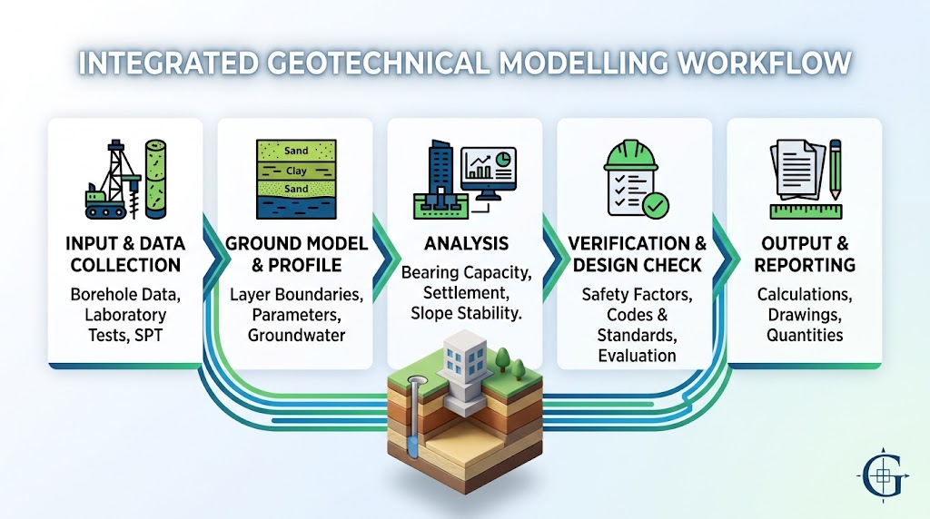
A practical workflow can be viewed as five connected stages:
1. Input
The process begins with the information that defines the ground and the engineering problem. This may include boreholes, soil layers and their engineering parameters, groundwater conditions, foundation or retaining-system geometry, and applied loads.
2. Model
These inputs are organized into an engineering representation of the site. The model should establish the ground profile, structural geometry, and the relationships between soil conditions and the elements interacting with them.
3. Analysis
The same model can then provide the basis for relevant geotechnical calculations, depending on the project. These may include bearing capacity and settlement analyses, pile behaviour, excavation support analysis, slope stability, and liquefaction assessment.
4. Verification
Calculation results must be interpreted against the applicable design requirements. Engineers may need to evaluate capacity, deformation, stability, safety factors, and compliance with the standards or design approaches adopted for the project.
5. Output
The workflow should ultimately translate the analysis into engineering deliverables: calculation results, tables and graphs, project drawings, quantity information, and technical reports.
The value of connecting these stages is consistency. When soil properties, groundwater conditions, geometry, or loads change, engineers should be able to evaluate their consequences without repeatedly rebuilding the project across disconnected calculation and documentation tools. In this sense, effective geotechnical modelling software is not simply a tool for creating a subsurface model; it provides a structured path from ground data to an engineering decision and, ultimately, a documented design.
An Integrated Workflow With SETAF2018
SETAF2018 follows this type of integrated workflow by allowing the engineer to build the ground model and carry the same project data through analysis, design, and reporting. Rather than treating soil characterization, geotechnical calculations, structural elements, and project documentation as entirely separate tasks, the software connects them within the same engineering environment.
Soil and Site Model
The workflow begins with an engineering-oriented representation of the site. Engineers can define multiple boreholes, soil layers, groundwater conditions, and user-defined material properties, together with field investigation data such as SPT and Menard Pressuremeter (MPM) profiles. Boreholes, foundations, retaining structures, and other defined project elements can then be examined in plan and 3D perspective views.
The purpose of this visualization is not geological modelling for its own sake. It provides a spatial framework for understanding how the interpreted soil profile relates to the engineering systems that will subsequently be analysed.
Foundation and Ground Improvement Analysis
The same project data can be carried into the analysis of shallow foundations, piles and micropiles, deep mixing columns, and jet-grouting systems. Depending on the problem, SETAF2018 can evaluate bearing capacity, immediate and consolidation settlement, pile-group behaviour, negative skin friction, and subgrade reaction parameters.
These calculations use established geotechnical approaches appropriate to different design problems. For example, shallow-foundation bearing capacity can be evaluated using methods such as Terzaghi, Meyerhof, and Vesić, while stress increases used in settlement calculations can be determined using Boussinesq or Mindlin–Geddes approaches. For deep foundations, skin and tip resistance can be evaluated using α, λ, and β methods.
Excavation and Slope Models
The workflow also extends to excavation support and stability problems. SETAF2018 can model systems incorporating bored pile walls, anchors, soil nails, reinforced concrete retaining walls, and structural supports, while accounting for earth pressures, groundwater, and surcharge effects.
For slope and excavated-face stability, limit-equilibrium approaches including Bishop and Fellenius can be used, with anchors and soil nails incorporated where applicable. These capabilities rely on established analytical and numerical engineering approaches rather than full nonlinear continuum FEM.
From Calculation to Deliverable
The workflow does not end when an analysis produces a result. SETAF2018 can generate engineering calculation reports, tables, charts, foundation and excavation-support drawings, reinforcement details, and quantity outputs. Drawings can be exported in DWG format, while applicable calculation and reinforcement tables can be exported to XLSX.
This means the same project model can remain connected from initial soil interpretation through design verification and engineering documentation, reducing the need to recreate the same project information across multiple disconnected tools.
Common Mistakes When Building Geotechnical Models
Even when reliable investigation data and appropriate analysis methods are available, modelling decisions can introduce uncertainty or produce results that do not adequately represent the actual engineering problem. Several common mistakes are worth avoiding.
Adding Complexity Without Engineering Purpose
More detail does not automatically create a better model. Introducing additional soil layers, parameters, geometric features, or analysis variables should have a clear engineering purpose. Unnecessary complexity can make results harder to interpret and may create a false impression of precision that is not supported by the available site investigation data.
Treating Borehole Data as Continuous Reality
Boreholes describe conditions at specific investigation locations. The soil boundaries drawn between them are interpretations, not direct observations of the entire subsurface. Changes in stratigraphy, ground elevation, and local soil conditions therefore require engineering judgement when constructing the model.
Ignoring Groundwater Variability
Groundwater should not automatically be represented by a single fixed level simply because one measurement is available. Seasonal variation, perched groundwater, artesian conditions, and project-specific groundwater observations may need consideration. Different groundwater assumptions can materially alter effective stresses and consequently influence bearing capacity, settlement, earth pressures, and stability calculations.
Using Parameters Outside Their Intended Context
A parameter should be selected for the behaviour being analysed. Soil strength parameters adopted for bearing-capacity calculations, for example, may not necessarily represent the stiffness or compressibility required for deformation and settlement analyses. Drained and undrained conditions must also be distinguished where relevant.
Trusting Software Output Without Verification
Software can make complex engineering calculations faster and more consistent, but numerical output alone does not validate the underlying model. Unexpected results should prompt engineers to review inputs, assumptions, units, groundwater conditions, geometry, and the selected calculation method.
Geotechnical software performs calculations; the engineer remains responsible for determining whether the model, parameters, assumptions, and results are appropriate for the project.
The Model Is Only as Useful as the Decision It Supports
A successful geotechnical model is not necessarily the one with the most soil layers, the most sophisticated visualization, or the longest calculation time. Its value lies in whether it represents the governing ground conditions and engineering mechanisms with sufficient accuracy to support a defensible design decision.
That requires engineering judgement at every stage. Borehole data must be interpreted into a representative soil profile, parameters must be selected for the behaviour being analysed, groundwater conditions must be considered, and the appropriate analytical or numerical method must be chosen for the specific problem. The results must then be checked against the relevant design requirements before they become part of the final engineering documentation.
In practical terms, the process remains:
Soil Data → Engineering Model → Analysis → Verification → Design Documentation
This is also where integrated geotechnical modelling software can provide practical value. Platforms such as SETAF2018 are designed around this engineering workflow, combining soil and project modelling with established geotechnical calculations, design checks, drawings, quantity outputs, and reporting within the same project environment.
The software can organize and perform the calculations, but the model remains an engineering interpretation. Ultimately, its reliability depends on whether the assumptions behind it adequately represent the ground, the structure, and the design question being evaluated.
FAQs About Geotechnical Modeling software
What is a geotechnical model?
A geotechnical model is an engineering representation of the ground conditions and the system being analysed. It typically combines interpreted soil stratigraphy, groundwater conditions, relevant mechanical properties, project geometry, and applied loads. Depending on the problem, it may also include foundations, piles, retaining structures, anchors, soil nails, or slope geometry. Its purpose is to simplify real subsurface conditions into a defensible model that can support engineering analysis and design decisions.
What is geotechnical modelling software used for?
Geotechnical modelling software helps engineers transform site investigation data into models that can be used for analysis and design. Borehole information, soil properties, groundwater conditions, structural geometry, and loads can be brought together to evaluate problems such as foundation bearing capacity, settlement, deep foundations, excavation support, and slope stability. Some platforms, including SETAF2018, also connect these analyses with design checks, engineering drawings, quantities, and reporting.
Is geotechnical modelling the same as finite element modelling?
No. Finite element modelling is one approach that can be used within geotechnical engineering, but geotechnical modelling is a broader concept. Many engineering problems can be evaluated using established analytical methods, limit-equilibrium methods, or numerical beam-and-spring models. Continuum FEM is particularly useful when advanced constitutive models, nonlinear soil behaviour, detailed construction stages, or complex deformation patterns need to be represented. The appropriate method depends on the engineering problem rather than on modelling complexity alone.
What data is required to create a geotechnical model?
Typical inputs include borehole logs, interpreted soil stratigraphy, groundwater observations, field and laboratory test results, and engineering parameters assigned to individual soil layers. Depending on the analysis, engineers may also need foundation dimensions, pile geometry, excavation depth, retaining-system elements, slope geometry, surcharge loads, and other project-specific conditions. The required data should ultimately reflect both the ground and the engineering system interacting with it.
How are boreholes used in geotechnical modelling?
Boreholes provide information about subsurface conditions at discrete locations across a site. Engineers compare soil descriptions, layer elevations, samples, and field test results from multiple boreholes to interpret how stratigraphy may vary between investigation points. Because the ground between boreholes has not been directly observed, the resulting layer boundaries involve engineering interpretation. A geotechnical model should therefore represent the available evidence without implying greater subsurface certainty than the investigation supports.
Why is groundwater important in geotechnical models?
Groundwater influences porewater pressure and effective stress, making it relevant to many geotechnical calculations. Changes in groundwater conditions can affect bearing capacity, settlement, lateral earth pressures, excavation behaviour, and slope stability even when the soil and structural geometry remain unchanged. Depending on site conditions, engineers may also need to consider effects such as capillarity or artesian pressure. Groundwater should therefore be incorporated into the ground model rather than treated simply as an isolated calculation input.
Which analyses can be performed from a geotechnical model?
The available analyses depend on the software, model, and requirements of the project. A geotechnical model may support shallow-foundation bearing capacity and settlement calculations, pile and pile-group evaluation, ground-improvement analysis, excavation support design, slope stability assessment, and liquefaction analysis. For example, SETAF2018 uses the defined ground and project information across several of these analysis types while also supporting subsequent design verification and engineering documentation.