A braced excavation is supported by compression members spanning between opposing walls, or between a wall and a foundation, rather than by tension elements installed into the ground behind it. The struts carry the earth and water pressure that the wall cannot resist on its own, transferring it across the excavation instead of into the surrounding soil.
Bracing is chosen where anchors cannot be used: where the ground behind the wall is not available, where adjacent structures or utilities prevent installation, where an anchor would cross a site boundary, or where the ground cannot develop the required bond capacity.
The design problem differs from anchor design in a way that is frequently underestimated. An anchor is a tension element, and tension members are governed by material strength alone. A strut is a compression member, and compression members are governed by stability — which introduces buckling, eccentricity, and a load case that has no equivalent in anchored systems.
A strut is a column, and it has to be designed as one.
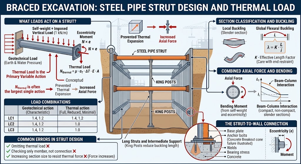
What Loads Act on a Strut?
| Action | Nature | Source |
|---|---|---|
| Geotechnical load | Permanent | Earth and water pressure transferred from the wall |
| Thermal load | Variable, primary | Restrained expansion of the steel section |
| Self-weight | Permanent | Section weight plus imposed vertical load along the span |
| Eccentricity moment | Consequence of detailing | Connection not free to rotate |
The geotechnical load comes from the wall analysis and is treated as a permanent action, since the earth pressure it represents does not vary with time in the way an imposed load does.
Self-weight includes the mass of the section itself plus an allowance for incidental vertical loading along the strut — commonly taken as a linear vertical load of about 1 kN/m to cover services, walkways, and construction activity. A long horizontal steel member spanning an excavation carries bending from its own weight before any external action is applied.
Eccentricity arises because the connection between strut and wall is not, in practice, a pin. It transfers moment, and the resulting eccentric loading is commonly represented by applying the axial force at an offset of about one sixth of the pipe diameter. This converts a nominally axially loaded member into a beam-column, which changes the governing check.
Why Thermal Load Is the Primary Variable Action
A steel strut installed on a cold morning and exposed to direct sun by mid-afternoon tries to expand. Both ends are restrained by walls that are themselves restrained by the ground. The expansion the member cannot achieve appears instead as axial force.
The characteristic thermal load is:
N_thermal = μ · α_T · ΔT · E · A
where α_T is the coefficient of thermal expansion of the steel, ΔT the temperature change relative to the installation temperature, E the elastic modulus, A the cross-sectional area, and μ the proportion of free length change that is actually restrained.
Two features of this expression deserve attention.
The area A appears in the numerator, so a heavier section attracts more thermal load. Increasing section size to resist thermal force therefore increases the force. This is one of the few situations in structural design where the obvious remedy makes the problem worse.
The restraint factor μ is the parameter that decides the magnitude, and it depends on the stiffness of everything the strut pushes against — the wall, the surrounding ground, and the connection detail. Full restraint is a conservative assumption that can produce a thermal force comparable to the geotechnical load itself.
Thermal load is not a secondary consideration in a braced excavation. It is often the largest single action on the strut.
This is why design codes and practice treat it as the primary variable action in every load combination rather than as an accompanying one.
Load Combinations
Three combinations are normally examined, each pairing the permanent geotechnical action with the thermal action at a different level:
| Combination | Geotechnical action | Thermal action |
|---|---|---|
| LC1 | Characteristic | Full |
| LC2 | Characteristic | Reduced |
| LC3 | Characteristic | Minimal |
The corresponding factors applied in the serviceability assessment decrease across the three cases, typically in the order 1.4, 1.2 and 1.0, reflecting the reducing contribution of temperature.
A stress redistribution coefficient is also applied. Where the analysis is capable of tracking how horizontal earth pressure changes as excavation stages proceed, this coefficient is unity, because the redistribution is already represented in the calculated forces. Where a simplified pressure diagram is used, an allowance is made instead.
Serviceability or Ultimate: Which Governs?
Two distinct force values arise.
The serviceability value is derived from the calculated wall forces without partial factors applied to the actions, then modified by the combination and redistribution coefficients described above.
The ultimate value is derived from the same analysis with partial factors applied to the actions, in accordance with the design approach adopted.
The strut is designed for the larger of the two. Neither can be assumed to govern in advance, because the combination coefficients applied to the serviceability case can exceed the partial factors applied to the ultimate case, particularly in LC1 where the full thermal action is present.
Section Classification and Buckling
Once the design force is established, the strut is designed as a steel compression member using a load and resistance factor approach.
Local Buckling Under Compression
Circular hollow sections are classified by the ratio of outside diameter to wall thickness. Above a limiting value that depends on the steel grade and elastic modulus, the section is slender and cannot develop its full yield capacity before the wall buckles locally.
For slender sections an effective area replaces the gross area in the capacity calculation, reflecting the portion of the wall that remains effective after local buckling.
Flexural Buckling
Global stability is governed by the slenderness ratio:
λ = K · L / i
where L is the strut length, i the radius of gyration of the section, and K the effective length factor reflecting the end restraint provided by the connections.
The characteristic axial compression resistance follows from the critical buckling stress, which is derived from the elastic buckling stress and depends on whether the section is slender. The design resistance is obtained by applying the resistance factor for compression.
The effective length factor deserves care in temporary works. Struts are frequently assumed pinned at both ends, but a connection stiff enough to transmit the eccentricity moment discussed earlier is not a pin, and consistency between the eccentricity assumption and the effective length assumption is worth checking.
Long Struts and Intermediate Support
Because capacity falls with the square of slenderness, long struts across wide excavations become inefficient rapidly. This is why king posts are introduced at intervals: not to carry vertical load, but to reduce the buckling length of the strut.
Combined Axial Force and Bending
A strut carries axial compression from the wall, bending from its own weight and any imposed vertical load, and additional bending from the connection eccentricity. It is therefore checked as a beam-column.
The bending resistance depends on section classification under flexure, with compact, non-compact, and slender sections treated differently and the resistance based on the plastic or elastic section modulus accordingly.
The interaction between axial force and bending is evaluated by the standard beam-column relationship, in which the two utilisations are combined with a weighting that depends on the level of axial load. Where axial force dominates, the bending contribution is weighted by a factor of eight ninths; where bending dominates, the axial contribution is halved.
Shear is also checked, using the critical shear stress for circular sections, which is taken as the larger of the values given by the two applicable expressions.
The Strut-to-Wall Connection
The connection is where most braced excavation failures originate, and it involves more checks than the member itself.
| Element | Check |
|---|---|
| Base plate | Bearing stress on concrete, plate dimensions, cantilever lengths |
| Plate thickness | Bending under the calculated bearing pressure and tension |
| Anchor bolts | Tensile capacity, minimum diameter, group behaviour |
| Concrete | Breakout cone failure, pullout, crushing beneath the plate |
| End plate | Bending of the anchor end plate |
| Welds | Capacity of the pipe-to-plate weld in shear and bending |
The eccentricity that was introduced into the member design reappears here as a moment at the connection. That moment produces tension in the bolts on one side of the plate and increased bearing on the other, which is why a critical eccentricity is calculated and the effective plate dimension adjusted before the concrete stress is evaluated.
Concrete breakout is the check most often omitted. An anchor bolt group in tension can fail by pulling out a cone of concrete rather than by yielding, and the resistance depends on embedment depth, edge distance, bolt spacing, whether the concrete is cracked, and the eccentricity of the applied tension. The projected failure areas of individual bolts overlap when spacing is close, which reduces group capacity below the sum of individual capacities.
Required plate thickness is governed by whichever of several mechanisms produces the largest value — bending of the cantilever outstands under bearing pressure, and bending induced by the bolt tension on the other side.
Waler Beams
Where struts are spaced more widely than the wall can span, a waler beam distributes the strut reaction along the wall.
The waler is designed as a continuous beam spanning between struts, carrying the distributed reaction from the wall. It can be a reinforced concrete beam cast against the wall or a steel section, commonly a channel profile, and the same connection considerations apply where it meets the strut.
Waler design is the point at which strut spacing is settled. Wider spacing reduces the number of struts and improves access within the excavation, but increases both the force in each strut and the span of the waler.
Common Errors in Strut Design
| Error | Consequence |
|---|---|
| Omitting thermal load or treating it as an accompanying action | The largest single action on the strut underestimated |
| Increasing section size to resist thermal force | Thermal force increases in proportion to area; the problem grows |
| Assuming a moment-free connection while detailing a stiff one | Eccentricity moment unaccounted for in a member checked as axially loaded |
| Using K = 1.0 without examining end restraint | Buckling capacity misestimated in either direction |
| Checking the member but not the connection | Failure mode moved to the least examined element |
| Omitting the concrete breakout check | Anchor group capacity overestimated, particularly at close spacing |
| Designing only the final excavation stage | Peak strut force in an intermediate stage missed |
Where SETAF2018 Fits
SETAF2018 designs steel pipe struts as part of the staged excavation analysis, so the force used in the member check is the force calculated at each construction stage rather than an assumed proportion of the earth pressure.
Struts are defined by elevation, horizontal spacing, length, and inclination where they are not perpendicular to the wall, with sections selected from a profile library or defined by outside diameter and wall thickness. The first or last strut in a row can be omitted where geometry requires it.
Load combinations LC1 to LC3 are evaluated with the thermal action as the primary variable action, using the thermal expansion coefficient, temperature change, and restraint percentage entered for the section. The design force is taken as the greater of the serviceability and ultimate values. Section classification, effective area for slender sections, flexural buckling, bending resistance, the axial-bending interaction, and shear are then checked against that force.
The connection is designed in the same pass: base plate dimensions and thickness, stiffeners, anchor bolt diameter and layout with the minimum bolt diameter enforced, concrete bearing and breakout, anchor end plate bending, and weld capacity. Results appear as a design summary with the governing check identified, and the underlying equations appear in the local design reports rather than only utilisation ratios.
Because struts, ground anchors, and soil nails all exist within the same wall section, a mixed support scheme can be analysed as one system, and the earth pressures that generate the strut forces come from the same model that produces the wall section design, drawings, and quantities. The full workflow is described in the excavation support analysis overview.
Frequently Asked Questions
What is a braced excavation?
It is an excavation supported by compression members spanning across the opening between opposing walls, rather than by anchors installed into the ground behind the walls. Bracing is used where the ground behind the wall is unavailable or unsuitable for anchors.
Why is thermal load so important in strut design?
Because a strut restrained at both ends converts prevented thermal expansion directly into axial force, and that force is proportional to the cross-sectional area and the elastic modulus of the steel. In exposed excavations the thermal action can be comparable to or larger than the geotechnical action.
Does a bigger strut section solve a thermal load problem?
Not straightforwardly. Thermal force is proportional to the cross-sectional area, so increasing the section increases the force it attracts. Reducing restraint, controlling installation temperature, or accepting a lower restraint factor with justification are more effective responses.
How is strut buckling checked?
By classifying the section for local buckling under compression, calculating the slenderness ratio from the effective length and radius of gyration, obtaining the critical buckling stress, and applying the resistance factor. Long struts are usually supported at intervals by king posts to reduce the buckling length.
Why is a strut checked as a beam-column?
Because it carries bending as well as axial force. Self-weight and imposed vertical load produce bending along the span, and the connection eccentricity produces additional moment. The two utilisations are combined through an interaction relationship rather than checked separately.
What is the eccentricity used in strut design?
The connection is not a true pin, so the axial force is applied at an offset from the centroid, commonly taken as about one sixth of the pipe diameter. This produces a moment that must be carried by both the member and the connection.
What should be checked at the strut-to-wall connection?
Bearing on the concrete, base plate dimensions and thickness, anchor bolt tension, concrete breakout and pullout, anchor end plate bending, and the weld between pipe and plate. Concrete breakout is the check most frequently omitted and can govern at close bolt spacing.
Should every construction stage be checked?
Yes. Strut forces change as excavation proceeds and as lower levels of support are installed. The maximum force in a given level frequently occurs before the excavation reaches its final depth.