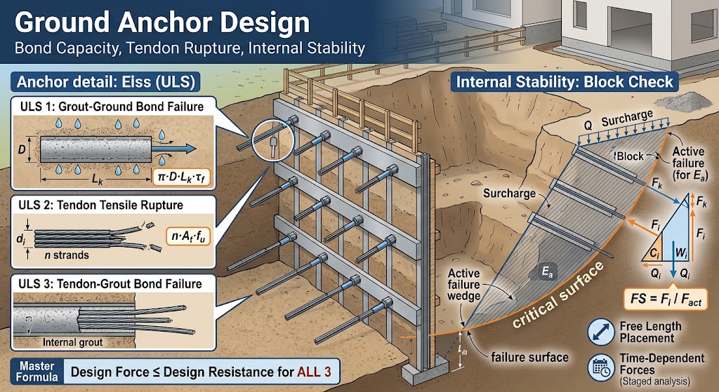
A ground anchor is a tensile element installed into the ground behind a retaining structure, transferring load from the structure into a grouted bond zone located beyond the soil mass that is trying to move. It consists of a tendon, a free length that transfers load without engaging the surrounding ground, and a bond length in which load is transferred to the soil or rock through the grout body.
Anchor design is not a single capacity calculation. An anchor can fail in three distinct ways, each governed by a different material and a different mechanism, and it can satisfy all three while still being installed into ground that is itself unstable.
Wall analysis → Anchor force → Three ULS checks → Internal stability block → Design
An anchor has three ways to fail, and the design is only as good as the weakest of them.
What Are the Components of a Ground Anchor?
| Component | Symbol | Function |
|---|---|---|
| Tendon | n, dᵢ | Steel strands or bars carrying tensile load |
| Free length | Ls | Transfers load past the potentially unstable zone without bonding to it |
| Bond length | Lk | Transfers load into the ground through the grout body |
| Bond zone diameter | D | Effective diameter of the grouted body |
| Inclination | α | Angle of the anchor below horizontal |
| Horizontal spacing | S | Centre-to-centre distance between anchors in a row |
| Prestress force | F | Force locked into the tendon at stressing |
| Head assembly | — | Bearing plate, wedge head, and where used a waler beam |
The distinction between free length and bond length is the defining feature of a ground anchor and separates it from a soil nail. The free length exists specifically so that load is delivered beyond the zone of ground that could move with the wall. Where that separation is absent, the element resists movement by being embedded within the moving mass rather than beyond it, which is a different mechanism with different design rules.
What Are the Three Ultimate Limit States?
Each failure mode involves a different interface or material, and each is checked separately against the anchor force obtained from the wall analysis.
| Limit state | Interface or material | Governed by |
|---|---|---|
| Grout–ground bond failure | Outer surface of the grout body | Soil or rock strength, bond length, bond diameter |
| Tendon tensile rupture | Steel tendon | Steel grade and cross-sectional area |
| Tendon–grout bond failure | Inner surface between steel and grout | Grout strength, embedded length, bar surface |
The design force must be less than the design resistance in all three. Which one governs varies with ground conditions: in weak soils the grout–ground bond usually controls and drives the required bond length, while in rock or very stiff ground the tendon itself frequently becomes the limiting element.
ULS 1: Grout–Ground Bond Capacity
This is the check most engineers mean when they refer to anchor pullout capacity. The ultimate resistance is the shear that can be developed over the outer surface of the grout body:
Tf = π · D · Lk · τf
where D is the effective diameter of the bond zone, Lk the bond length, and τf the ultimate skin friction at the grout–ground interface.
The bond diameter deserves care. In pressure-grouted anchors the grout body expands beyond the drilled hole, so the effective diameter exceeds the nominal borehole diameter — but by an amount that depends on grouting pressure, method, and ground conditions, and that should be justified rather than assumed.
The ultimate skin friction can be established in four ways, and the choice reflects how much information is available.
From Effective Stresses
For drained conditions in granular soils:
τf = K₁ · σ′v · tan φ′
where σ′v is the vertical effective stress at the mid-point of the bond length, φ′ the effective friction angle of the soil, and K₁ a lateral earth pressure coefficient reflecting the installation method.
For anchors installed without grouting pressure, K₁ typically falls between 1.4 and 2.3. In fine sands and silty soils it can drop to between 1.0 and 1.5 depending on relative density. The coefficient is where the installation method enters the calculation, and it is the parameter most often carried over from a different project without checking that the method matches.
From Total Stresses
For undrained conditions in fine-grained soils:
τf = αa · Su
where Su is the average undrained shear strength along the bond length and αa an adhesion factor. The same reasoning applies as in pile shaft resistance: the factor declines as undrained strength increases, because stiff clays do not develop the full strength at the interface.
From Empirical Data
Published tables give ranges of ultimate skin friction by soil description and installation method, separately for cohesive soils, cohesionless soils, and rock. These are the most commonly used values in practice and the basis of FHWA guidance. Because they are ranges derived from case histories rather than site-specific measurements, an additional empirical safety coefficient is normally applied.
From Pull-out Testing
Where anchor testing is carried out on the project, the measured capacity supersedes all of the above. This is the only route that reflects the actual ground and the actual installation method, which is why testing regimes are specified for permanent anchors and for large temporary works.
ULS 2: Tendon Tensile Rupture
The tendon must not yield or rupture under the design force. The resistance follows directly from the steel:
Fu = n · At · fu
where n is the number of strands or bars, At the nominal cross-sectional area of one, and fu its nominal tensile strength.
This check is arithmetically simple, and for that reason it is sometimes treated as a formality. It should not be. It becomes the governing limit state in competent ground, where a short bond length in rock develops more capacity than the steel can carry, and it is the check that determines whether an anchor with adequate ground capacity has been detailed with enough strands to use it.
ULS 3: Tendon–Grout Bond
The third interface lies inside the grout body, between the steel and the grout that surrounds it. Load transferred from the ground to the grout must still reach the tendon.
The resistance depends on the bond stress developed between steel and grout, the embedded length, and the surface area of the tendon. Bond stress is derived from the tensile strength of the grout, following either TS 500 or ACI 318 provisions, with ribbed and plain surfaces treated differently.
This check applies to strand and bar anchors bonded within a grout body. It governs less often than the other two, but when it does, the consequence is a failure mode that occurs entirely inside the anchor and cannot be detected by inspecting the ground.
Where Must the Bond Length Begin?
Satisfying all three capacity checks is not sufficient if the bond zone is in the wrong place.
The free length exists to carry load past the soil that could move with the wall. If the bond zone begins within that zone, the anchor is transferring load into ground that is itself being retained by the anchor — a circular arrangement that provides far less restraint than the calculation suggests, and in the limit provides none.
The boundary of the potentially unstable zone is defined by the active failure surface behind the wall, which depends on the earth pressure state and the friction angle of the ground. The bond zone must begin beyond it, with a margin, and the free length must be long enough to reach that point at the chosen inclination.
Anchor inclination interacts with this requirement. A steeper anchor reaches beyond the failure surface with a shorter free length, but delivers less of its force horizontally where the wall needs it, and introduces a larger vertical component into the wall — which must be carried by the wall in axial compression and can matter for slender sections.
What Is Anchor Internal Stability?
Capacity and stability are different questions. The three ULS checks confirm that an anchor of given dimensions can carry a given force. Internal stability asks a separate question: whether the block of ground containing the anchor is itself in equilibrium.
An anchor can be entirely adequate in capacity and still be anchored into ground that is moving.
The check is carried out by analysing a block of ground bounded by a plausible failure surface passing beneath the wall and through the anchor bond zone. In its usual construction, the block is defined by connecting the theoretical toe point of the wall to the mid-point of the anchor bond length, and rising from that point to the ground surface.
At the theoretical toe point, the resultant of horizontal forces acting on the wall below excavation level is zero, which is what makes it the appropriate lower boundary for the block.
The forces acting on that block are:
| Force | Meaning |
|---|---|
| Ea | Resultant of active pressures acting on the wall over the block height |
| Eai | Resultant of active earth pressure above the bond zone of the anchor being verified |
| Wi | Weight of the block |
| Ci | Cohesive resistance along the inclined slip surface |
| Qi | Reaction on the slip surface |
| Fj, Fk … | Forces from other anchors that intersect the block |
| Fi | Maximum permissible force in the anchor being verified |
Writing vertical and horizontal equilibrium for the block yields Fi, the largest force the verified anchor can carry while the block remains in equilibrium. The factor of safety follows:
FS = Fi / F
where F is the force actually calculated in that anchor by the wall analysis.
Which Other Anchors Are Included?
An anchor row does not act alone, and other anchors contribute to the equilibrium of the block only if they genuinely cross it. Two rules determine inclusion.
For anchors below the one being verified, a slip surface is constructed from the toe point to the bond zone and then to the ground surface at an inclination of (45° − φ/2). If the bond zone of the anchor being verified lies outside that surface, the lower anchor is included in the analysis.
For anchors above the one being verified, the slip surface constructed for the verified anchor is used. If the bond zone of the upper anchor lies inside that surface, it is included.
The check is repeated for every active anchor at every construction stage. This matters because the governing case is frequently an intermediate stage — a row that has been stressed while the excavation below it is still shallow, before the lower rows exist to share the load.
How Are Anchors Modelled in a Staged Analysis?
The force in an anchor is not an input to the wall analysis. It is a result, and it changes as construction proceeds.
In the stage in which a prestressed anchor is stressed, it is introduced as a force acting on the wall at that node — the wall has already deformed under the preceding excavation, and the anchor is installed into that deformed geometry.
In every subsequent stage, the same anchor acts as a spring carrying that force. As the wall continues to deflect during deeper excavation, the anchor extends and its force changes accordingly. The spring stiffness follows from the axial stiffness of the tendon, its length and inclination, and the horizontal spacing between anchors in the row.
Anchors installed without prestress are modelled as springs in every stage, since they develop force only through wall movement.
The practical consequence is that the maximum force in a given anchor row usually does not occur in the final excavation stage. It occurs at whichever stage produces the greatest wall deflection at that level, which is why all stages must be checked rather than only the completed condition. The framework within which these forces develop, and the way soil reaction is represented, are discussed in the guide to the modulus of subgrade reaction.
How Much Prestress?
Prestress determines when an anchor’s capacity is used, not how much of it exists.
A heavily prestressed anchor restrains wall movement from the outset, which limits ground settlement behind the wall and protects adjacent structures. It also attracts load: the wall becomes stiffer at that level, earth pressures redistribute toward it, and the anchor may end up carrying more than it would otherwise.
A lightly prestressed anchor allows more wall movement, permits earth pressures to relax toward the active state, and attracts less load — but the movement it permits may exceed what neighbouring structures tolerate.
Prestress does not increase capacity. It decides when the capacity is used, and how much movement occurs before it is.
The choice is therefore a serviceability decision as much as a strength one, and it is made by examining wall deflection and ground settlement behind the wall across all construction stages rather than by applying a fixed proportion of the design load.
Common Errors in Ground Anchor Design
| Error | Consequence |
|---|---|
| Bond zone beginning inside the active failure wedge | Anchor loads the ground it is restraining; restraint substantially less than calculated |
| Checking only the final excavation stage | Peak anchor force in intermediate stages missed |
| Using an effective bond diameter larger than the installation method justifies | Pullout capacity overestimated in direct proportion |
| Carrying K₁ over from a project with a different grouting method | Skin friction misestimated at the most sensitive parameter |
| Checking capacity but not internal stability | Adequate anchors installed into a block that is not in equilibrium |
| Ignoring the vertical component of anchor force | Axial load on the wall not accounted for in the section check |
| Treating tendon rupture as a formality | Governing limit state missed in competent ground |
Where SETAF2018 Fits
SETAF2018 treats anchor design as part of the staged wall analysis rather than as a separate calculation performed afterwards.
Anchors are defined by elevation, horizontal spacing, inclination, number and diameter of strands, bond zone diameter, free length, and bond length, together with the plate, head, and waler beam details required for the connection. Rows can be staggered, and the first or last anchor in a row can be omitted where geometry requires it.
The three ultimate limit states are evaluated for every anchor at every construction stage using the force obtained from the wall analysis at that stage. Ultimate skin friction can be entered directly, taken from empirical tables with a safety coefficient, or calculated from effective or total stress parameters using the layers the bond zone actually passes through. Tendon–grout bond resistance follows TS 500 or ACI 318 provisions, or a user-defined value.
Internal stability is analysed as a block for every active anchor in every stage, with the inclusion rules for adjacent anchors applied automatically and the resulting blocks displayed graphically alongside the calculated factor of safety. Vertical displacement of the ground behind the wall is evaluated from the calculated wall deflections, which is what allows prestress to be selected against a settlement criterion rather than a rule of thumb.
Because the anchor forces come from the same model as the earth pressures and the wall section design, changing an anchor level or a prestress force propagates through the pressure diagram, the structural forces, the connection design, and the drawings without re-entry. The equations behind each check appear in the local design reports rather than only the utilisation ratios, and worked examples of anchored bored pile systems are available in the case studies. The full workflow for anchored and braced systems is described in the excavation support analysis overview.
Frequently Asked Questions
What is a ground anchor?
It is a tensile element installed into the ground behind a retaining structure, consisting of a tendon, a free length that transfers load past the potentially unstable soil, and a grouted bond length that transfers load into stable ground beyond it. Ground anchors and tiebacks refer to the same element.
What is the difference between free length and bond length?
The free length is deliberately unbonded so that load passes through the zone of ground that could move with the wall. The bond length is grouted to the surrounding ground and is where load is actually transferred. Only the bond length contributes to pullout capacity.
How is anchor pullout capacity calculated?
From the surface area of the grout body multiplied by the ultimate skin friction at the grout–ground interface: Tf = π · D · Lk · τf. Skin friction is obtained from effective stress parameters, undrained shear strength, published empirical tables, or site-specific pull-out testing.
What are the three failure modes of a ground anchor?
Grout–ground bond failure, in which the grout body pulls out of the soil; tendon tensile rupture, in which the steel itself fails; and tendon–grout bond failure, in which the steel pulls out of the grout body. All three must be checked against the design force.
What is anchor internal stability?
It is a check on whether the block of ground containing the anchor bond zone is in equilibrium, carried out by analysing a block bounded by a slip surface through the wall toe and the bond zone. An anchor with adequate capacity can still be inadequate if the ground it is anchored into is not stable.
How deep must the bond zone be placed behind the wall?
Beyond the active failure surface, with a margin. The position of that surface depends on the friction angle of the ground and the geometry of the excavation. A bond zone that begins within the failure wedge transfers load into the same soil mass the anchor is restraining.
Does more prestress make an anchor stronger?
No. Prestress does not change capacity. It determines how much wall movement occurs before the anchor takes load, which affects settlement behind the wall and how earth pressures redistribute. Higher prestress reduces movement but attracts more load to that anchor level.
Why must every construction stage be checked?
Because anchor forces change as excavation proceeds and the wall deflects. The maximum force in a given row frequently occurs at an intermediate stage rather than at the final excavation level, particularly for upper rows stressed before the lower rows exist.