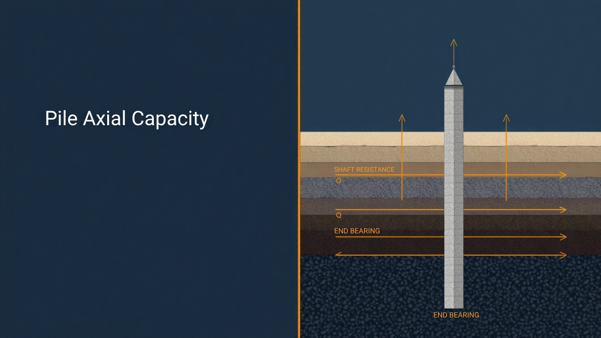
Pile axial capacity is the maximum load a pile can transfer to the ground before failure, made up of shaft resistance developed along its length and end bearing developed at its base. For a floating pile, the ultimate capacity is:
Qu = Qs + Qb − Wp
where Qs is the shaft resistance, Qb the end bearing, and Wp the net weight of the pile after allowing for buoyancy.
The two components are calculated by different methods, and which method applies depends on the drainage condition of each layer the pile passes through rather than on the pile itself. A single pile through layered ground is normally calculated layer by layer, with the total shaft resistance summed across all of them.
These methods apply beyond conventional piles. Micropiles, concrete piles, jet grout columns, and deep soil mixing columns all transfer load through the same two mechanisms, and the same calculations apply with the appropriate material and geometric properties.
Shaft and Base Resistance Do Not Arrive Together
Before considering the methods, one behavioural point governs how their results should be used.
Field testing consistently shows that full shaft resistance mobilises at very small relative displacement — of the order of 2.5 to 10 mm — while full end bearing requires displacement of about 8 to 10 per cent of the pile diameter. For a 600 mm pile, that is roughly 50 to 60 mm.
Shaft and base resistance are not two halves of one capacity. They arrive at different times.
At working load, shaft resistance is usually close to fully mobilised while base resistance has barely begun. Simply adding the two ultimate values gives a capacity that is real at large displacement but not available at the settlement a structure can tolerate. This is why serviceability frequently governs pile design, and why the two components are given separate spring stiffnesses when a pile group is analysed in a structural model using the modulus of subgrade reaction.
The Alpha Method: Shaft Resistance in Undrained Conditions
The alpha method calculates shaft resistance in fine-grained soils under short-term, undrained conditions using total stress parameters.
fs = α · Su
where Su is the undrained shear strength of the layer and α an adhesion factor.
The unit shaft friction is then multiplied by the shaft area within that layer, and the contributions summed:
Qs = Σ ( α · Su · As )
The adhesion factor is not a constant. It declines as undrained shear strength increases, and is commonly expressed as a function of the ratio of undrained strength to vertical effective stress. In soft normally consolidated clay, α approaches unity — the full undrained strength is developed at the pile surface. In stiff overconsolidated clay, α can fall to half that value or below, because installation disturbs the soil at the interface and the pile cannot develop the intact strength of the surrounding material.
The alpha method is a short-term calculation. It describes capacity immediately after installation, before excess pore pressures generated by installation have dissipated.
The Lambda Method: An Alternative for Undrained Conditions
The lambda method offers a different route to shaft resistance in undrained conditions, relating the maximum friction stress to the undrained shear strength through a coefficient that reflects the compressibility of the pile relative to the soil and the length over which load is transferred.
The formulation brings in the elastic modulus of the pile, its diameter, its effective embedded length, and the cross-sectional area, together with the relative movement required to mobilise shaft friction — conventionally taken as about 3 mm.
Its practical value is that it recognises what the alpha method treats as fixed: that the distribution of load transfer along a pile depends on the relative stiffness of pile and soil, and that a long compressible pile does not mobilise its full shaft friction simultaneously along its whole length.
Alpha remains the default in most practice. Lambda is a useful alternative where pile compressibility is significant.
The Beta Method: Shaft Resistance in Drained Conditions
For long-term drained conditions, and for granular soils at all times, shaft resistance is calculated in effective stress terms.
fs = β · σ′v
where σ′v is the vertical effective stress at the depth considered and β combines the lateral stress acting on the pile with the friction developed at the interface:
β = K · tan δ
with K the coefficient of lateral earth pressure against the shaft after installation and δ the interface friction angle between pile and soil.
For fine-grained soils, the lateral coefficient reflects stress history:
K = ( 1 − sin φ′ ) · OCR^(sin φ′)
For coarse-grained soils, an overconsolidation ratio of unity is normally assumed, reducing this to Jaky’s expression.
Selecting the Interface Friction Angle
The interface friction angle δ is bounded by the effective friction angle of the soil and is generally taken as a fraction of it, with the fraction depending on soil type and density:
| Soil condition | Guidance on δ |
|---|---|
| Soft fine-grained | Up to about one third of φ′ |
| Firm to stiff fine-grained, and loose to medium coarse-grained | Intermediate values |
| Dense coarse-grained | Generally not exceeding half of φ′ |
Because β multiplies the vertical effective stress, shaft resistance in this method increases with depth. This has a consequence worth noting: the deeper portion of a long pile contributes disproportionately to shaft capacity, so shortening a pile reduces capacity faster than proportionally.
Whether to Include Effective Cohesion
Effective cohesion can be included in the beta calculation, adding a depth-independent term. Whether to do so is a judgement. Small values of c′ derived from a best-fit line through triaxial results may not represent real available resistance at a pile interface, and many practitioners set c′ to zero for shaft resistance in the drained case as a matter of policy.
End Bearing
End bearing is calculated from the strength of the material at the pile toe.
In undrained conditions:
fb = Nc · Su
where Nc is a bearing capacity factor, commonly taken as 9 for deep foundations, or derived from expressions that account for the depth-to-diameter ratio and the shape of the base.
In drained conditions, end bearing follows from the effective overburden pressure at the base multiplied by a bearing capacity factor that depends strongly on the friction angle. The base resistance is then:
Qb = fb · Ab
with Ab the cross-sectional area of the base.
Two cautions apply. End bearing calculated in granular soils is sensitive to the friction angle, which is itself usually estimated from correlations, so the result carries substantial uncertainty. And a pile whose toe sits in a competent layer with a weaker layer a short distance below can punch through, so the material beneath the toe matters as well as the material at it.
Group Efficiency
Piles in a group do not each carry what an isolated pile would. Their zones of influence overlap, and the group as a whole may fail in a mode no single pile exhibits.
Qu,group = Eg · np · Qu
where np is the number of piles and Eg the group efficiency.
The Geometric Approach: Converse–Labarre
The Converse–Labarre expression estimates efficiency from the geometry of the group alone — the number of rows and columns, the pile diameter, and the centre-to-centre spacing. Efficiency decreases as spacing reduces relative to diameter and as the group becomes larger.
Its attraction is simplicity, and it captures the correct trend. Its limitation is that it makes no reference to soil type, and the physical mechanism of group interaction differs between granular and cohesive soils — in dense sand, driven pile groups can exhibit efficiency above unity because installation densifies the soil between them.
The Block Approach: Terzaghi
The block method addresses the second failure mode directly. The piles and the soil between them are treated as a single block, and the capacity of that block is calculated from shear resistance around its perimeter plus bearing on its base area.
The group capacity is then taken as the lesser of the sum of individual pile capacities and the block capacity. In closely spaced groups in soft cohesive soil, the block mode frequently governs, and the difference can be substantial.
A pile group has two ways to fail: pile by pile, or as a block. The design capacity is the lesser.
Common Errors
| Error | Consequence |
|---|---|
| Adding ultimate shaft and base resistance for a working-load check | Capacity credited that requires displacement the structure cannot tolerate |
| Using the alpha method for a long-term condition | Short-term capacity applied to a permanent load case |
| Applying a single α or β through a layered profile | Layers contributing very differently treated identically |
| Including effective cohesion in drained shaft resistance without justification | Depth-independent resistance added that may not exist |
| Checking individual pile capacity but not block capacity | The governing failure mode of a closely spaced group missed |
| Ignoring a weak layer below the toe | Punching failure through the bearing stratum not identified |
| Treating group efficiency as purely geometric in all soils | Cohesive and granular behaviour differ in mechanism and in sign |
Where SETAF2018 Fits
SETAF2018 calculates axial capacity layer by layer, selecting the method according to the drainage condition assigned to each layer in the soil profile rather than applying one method to the whole pile.
Shaft resistance in drained layers is calculated by the beta method, with the option to include or exclude effective cohesion. In undrained layers it is calculated by the alpha method by default, with the lambda method available as an alternative. End bearing in an undrained bearing stratum uses the alpha approach with the bearing capacity factor derived from Skempton’s expressions or entered directly.
Group efficiency is calculated either geometrically by Converse–Labarre or by the Terzaghi block approach, and the block check is applied so that the lesser of the two capacities governs. Results are reported as characteristic shaft, base, and total resistance, with resistance factors applied to give design values and the calculated factor of safety shown alongside.
Load distribution among the piles is calculated separately, from the axial force and the moments acting on the cap, assuming a rigid cap and pinned connections, which identifies the most heavily loaded pile in the group — the value that governs the capacity check and the settlement calculation. Where compressible layers surround the upper part of the piles, negative skin friction is evaluated and the neutral plane located.
Capacity is only part of the design. The same model produces the settlement of the pile group, the shaft and base spring stiffnesses for structural analysis, reinforcement design to TS 500, and the pile layout drawings and quantity schedules. Calculation equations and code references appear in the reports, and the overall workflow is described in the foundation analysis overview.
Frequently Asked Questions
What is pile axial capacity?
It is the maximum axial load a pile can transfer to the ground, made up of shaft resistance along its length and end bearing at its base, less the net weight of the pile itself.
What is the difference between the alpha and beta methods?
The alpha method is a total stress calculation for undrained conditions, taking shaft friction as a factor times the undrained shear strength. The beta method is an effective stress calculation for drained conditions, taking shaft friction as a factor times the vertical effective stress. Which applies depends on the drainage condition of the layer, not on the pile type.
When is the lambda method used?
As an alternative to the alpha method in undrained conditions, particularly where pile compressibility affects how load is distributed along the shaft. It brings in the pile’s elastic modulus and effective embedded length rather than treating shaft friction as uniform.
Do shaft and base resistance mobilise at the same displacement?
No. Full shaft resistance develops at roughly 2.5 to 10 mm of relative movement, while full end bearing requires displacement of about 8 to 10 per cent of the pile diameter. At working load, shaft resistance is largely mobilised and base resistance is not.
What is pile group efficiency?
It is the ratio between the capacity of a pile group and the sum of the capacities of the individual piles. It accounts for overlapping zones of influence and is calculated geometrically by expressions such as Converse–Labarre, or by comparing individual capacity against block failure of the group.
What is the Terzaghi block method?
It treats the piles and the soil between them as a single block, calculating capacity from shear resistance around the block perimeter plus bearing on its base. The group capacity is the lesser of the block capacity and the sum of individual capacities, and the block mode often governs in closely spaced groups in soft cohesive soil.
Do these methods apply to jet grout and deep mixing columns?
Yes. Rigid inclusions formed by ground improvement transfer load by the same shaft and base mechanisms, and the same calculations apply with the appropriate column geometry and material properties.
Is capacity or settlement usually the governing criterion?
Settlement governs more often than engineers expect, precisely because base resistance requires large displacement to mobilise. A pile group can satisfy every capacity check and still settle more than the structure accepts.