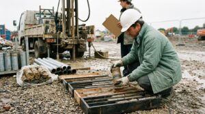
A three-dimensional geotechnical model is a spatial representation of the ground and the structures placed in it: a terrain surface, stratigraphy interpolated between boreholes, groundwater, and the walls, anchors, supports and foundation elements positioned in real coordinates. It is what the engineer looks at, and it is what the drawings are generated from.
What it is not, in most geotechnical software, is what the analysis runs on. That distinction is the single most misunderstood point in 3d geotechnical modelling software, and it is worth stating before anything else.
A model can be three-dimensional while the analysis remains sectional. The geometry, the quantities and the drawings come from the solid model; the stability and deformation calculations are performed on plane sections cut through it. This is not a limitation that was overlooked. For the great majority of retaining and foundation problems it is the appropriate level of analysis, and the results are the ones the codes are calibrated against.
A 3D model is a description of the site. A 3D analysis is a claim about how the site behaves. They are different things, and only one of them is usually necessary.
Where Does the Model Come From?
Three data sets, each with a different reliability.
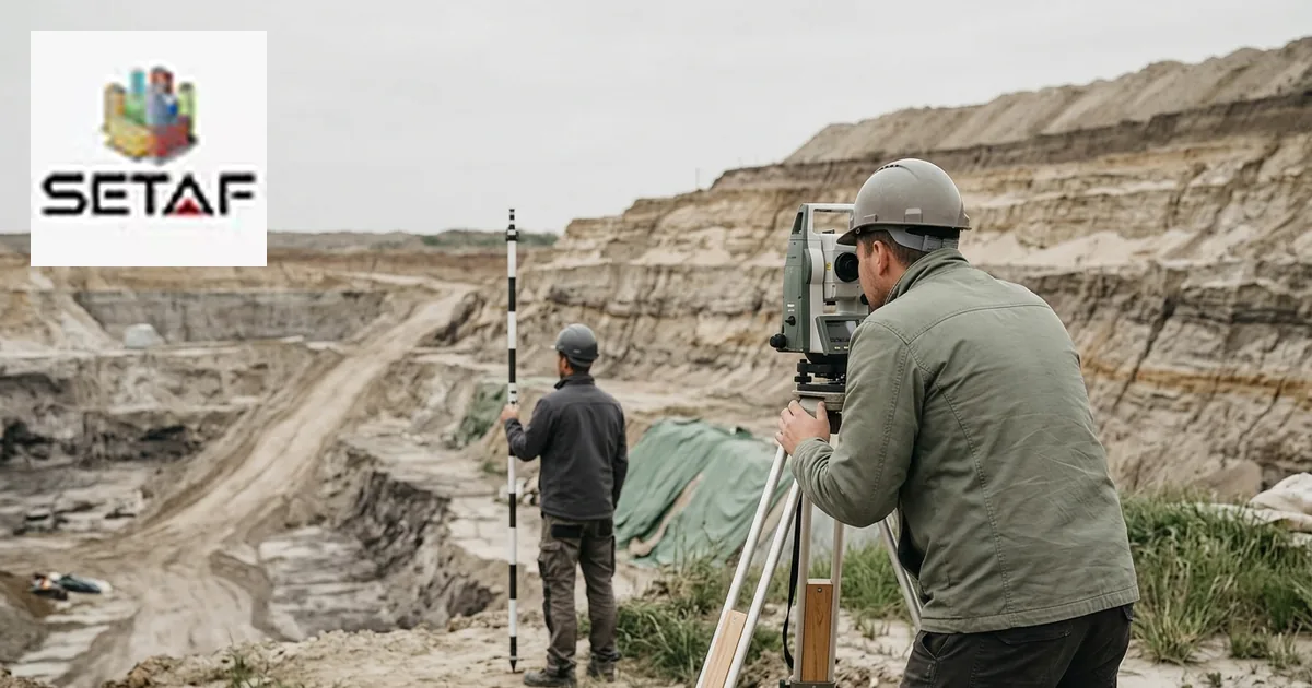
The terrain surface comes from survey: total station, GNSS or photogrammetry. It is the most accurate part of the model, because it is measured directly and densely.
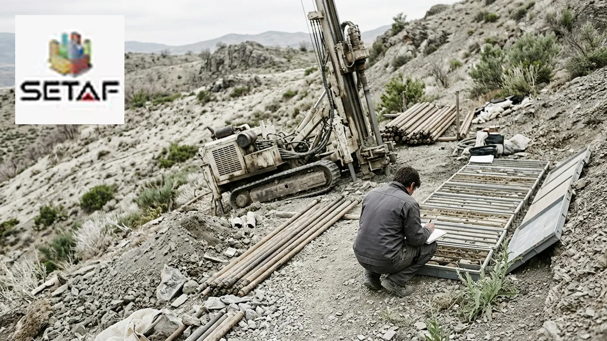
The stratigraphy comes from boreholes, and it is measured only at the borehole positions. Everything between them is interpolation. A model showing a clean clay layer running smoothly across a site is showing an assumption, drawn with the same confidence as the survey data beside it.
The structure comes from the design: wall alignments, pile positions, anchor inclinations, support levels. This part is exact by definition, because it is a decision rather than a measurement.
Mixing the three in one picture is what makes a 3D model useful and what makes it dangerous. The image does not distinguish measured ground from interpolated ground.
What Does 3D Geometry Actually Provide?
| Capability | What it depends on |
|---|---|
| Correct section geometry at any location | Terrain surface and stratigraphy in 3D |
| Consistent drawings across all sections | Model-generated views |
| Quantity take-off from real member geometry | Solid elements rather than lines |
| Clash detection between anchors, piles and boundaries | Elements in true coordinates |
| Staged excavation volumes | Terrain plus excavation geometry per stage |
| Communication with the client and the contractor | A view of the whole scheme |
None of these requires a three-dimensional analysis. All of them require a three-dimensional model.
The second item is the one that repays the modelling effort fastest. A section taken from a solid model has the ground surface, the layer boundaries and the groundwater level as they exist at that chainage, rather than as they were assumed when the section was drawn by hand.
Why Is the Analysis Still Sectional?
Because a plane section is a good representation of a problem that is long compared with its cross-section, and most retaining structures are.
A shoring wall running fifty metres along a site boundary, supported at the same levels throughout, behaves at its mid-length almost exactly as a plane strain analysis predicts. The soil cannot escape sideways, the wall cannot span horizontally in any useful way, and the third dimension contributes nothing the analysis is missing. Running a three-dimensional calculation on that geometry produces the same answer at considerably greater cost.
The sectional approach also has a practical advantage that is easy to undervalue: it is checkable. A beam-on-spring model with dependent pressures produces earth pressure diagrams, spring reactions and member forces that an engineer can examine and a reviewer can reproduce. A three-dimensional continuum result is harder to interrogate and harder to defend when a single number in it looks wrong.
When Does a Section Stop Representing the Problem?
At the places where the geometry stops being long and uniform.
Corners are the clearest case. At a re-entrant corner the soil is restrained in two directions and the real earth pressure differs from the plane strain value. Deep shafts and circular excavations are another: hoop action carries a large share of the load, and a plane section cannot represent it at all. Short walls, where the length is comparable with the depth, sit in between.
Other cases are less obvious. A wall with a ramp cut through it, an excavation with a large plan irregularity, a foundation immediately adjacent to a deeper one, and any situation where an existing structure sits close enough to interact three-dimensionally with the works all move the problem beyond what a section describes.
The engineering judgement is not whether the ground is three-dimensional. It always is. The judgement is whether the particular thing being calculated is sensitive to that.
What Does Three-Dimensional Analysis Add?
Continuum behaviour that a section cannot carry: load redistribution around corners, hoop action in shafts, interaction between closely spaced structures, and deformation fields around irregular geometry.
It adds them at a cost. A three-dimensional finite element analysis requires a constitutive model whose parameters have to be derived and justified, a mesh whose density affects the answer, and interpretation by someone who can tell a numerical artefact from a soil response. On a project where the geometry does not demand it, that effort buys precision in a place where the uncertainty is dominated by the ground parameters rather than by the analysis method.
Where the geometry does demand it, nothing else will do. The honest position is that three-dimensional finite element software and sectional design tools are complementary rather than competing, and that the choice is made by the problem.
How Is the Ground Surface Built From Boreholes?
By interpolating between known points, which means choosing an interpolation.
Layer boundaries are surfaces fitted through the depths recorded in each borehole. The fit depends on the method, on how the boreholes are distributed, and on whether the engineer intervenes to impose geological sense on the result. Automatic interpolation between four boreholes across a large plot produces a smooth surface that may have nothing to do with a buried channel running diagonally beneath it.
This is why the contour and surface model should be read as a hypothesis. The useful discipline is to look at the model with the borehole positions shown, and to ask whether the surfaces are supported by data or by the algorithm.
Why Do Two Models of the Same Site Differ?
Because three choices sit between the borehole logs and the model, and none is determined by the data.
The first is layer grouping: whether two similar strata are modelled as one unit or two changes every subsequent section. The second is interpolation, as above. The third is what to do with contradictory logs, which happens more often than model images suggest, and the resolution is a judgement about which borehole is representative.
A model built by a different engineer from the same logs will not be identical. What matters is whether the choices were recorded, so that a reviewer can disagree with the model rather than only with the result.
What Should Be Checked Before Analysis?
Four things, quickly.
That the borehole positions are plotted with the model, so interpolated ground is visibly distinguished from measured ground. That the groundwater surface is modelled rather than taken as a single level, where the site has a gradient or artesian conditions. That the sections chosen for analysis are the governing ones, which usually means the deepest excavation, the lowest ground level in front of the wall and the heaviest surcharge, and not necessarily all at the same chainage. And that the structural elements are at their real coordinates rather than at idealised spacings, because clash detection is only as good as the positions entered.
Common Errors in 3D Geotechnical Modelling
| Error | Consequence |
|---|---|
| Interpolated strata presented with the same confidence as survey data | Assumption read as a finding |
| Sections cut at convenient chainages rather than governing ones | The critical case is never analysed |
| Groundwater taken as a single horizontal level on a sloping site | Effective stresses wrong along most of the wall |
| Corners and shafts analysed as plane sections | Two-dimensional result applied where hoop or corner action governs |
| Three-dimensional analysis used where geometry does not require it | Effort spent on precision the ground parameters cannot support |
| Model geometry idealised for drawing convenience | Clash detection and quantities both inherit the idealisation |
| Contradictory borehole logs resolved silently | Reviewer cannot see which log was treated as representative |
Where SETAF2018 Fits
SETAF2018 builds the project as a three-dimensional model and analyses it on sections, and it is explicit about that division rather than presenting one as the other.
The ground is modelled from an unlimited number of boreholes, each with unlimited layers, carrying SPT records with their corrections, pressuremeter profiles where used, and groundwater conditions including artesian pressure and capillarity. Terrain and stratigraphy are built into a soil profile that every calculation reads, and the terrain model carries the surface geometry.
Excavation support is modelled in three dimensions through wall group macros: reinforced concrete or piled walls, steel strand anchors or reinforced concrete soil nails, and steel pipe, profile or concrete supports at their levels. Foundations are placed as rectangular, circular or polygonal elements with piles, micropiles, deep mixing or jet grout columns at real coordinates.
The analysis is performed on sections through that model using the dependent pressures method with elasto-plastic Winkler springs, stage by stage through the construction sequence. Drawings and quantities are generated from the solid model, so geometry and analysis stay consistent.
What the software does not do is three-dimensional finite element analysis of the excavation, nonlinear continuum soil models or probabilistic slope analysis. For corner-dominated geometry, deep shafts or close interaction with existing structures, a dedicated finite element package remains the right tool, and the two are used alongside each other on the projects that need both. The excavation support workflow is built for the standard geometries that make up most of the work rather than for the exceptions.
Frequently Asked Questions
What is a 3D geotechnical model?
It is a spatial representation of the ground and the structures in it: a surveyed terrain surface, stratigraphy interpolated between boreholes, groundwater, and the walls, anchors, supports and foundation elements at their real coordinates. It is the source of sections, drawings and quantities.
What is the difference between 3D modelling and 3D analysis?
Modelling describes the geometry; analysis calculates behaviour. A model can be three-dimensional while the analysis is performed on plane sections cut through it. Three-dimensional analysis solves the soil as a continuum in all directions and is a substantially larger undertaking.
Is sectional analysis less accurate than 3D analysis?
Not for geometry that is long and uniform compared with its cross-section, which covers most retaining walls and foundations. There the plane strain assumption is appropriate and the codes are calibrated against it. Accuracy diverges at corners, shafts, short walls and irregular plan geometry.
When is 3D finite element analysis actually necessary?
Where the third dimension carries load: re-entrant corners, circular shafts where hoop action governs, walls whose length is comparable with their depth, large plan irregularities, and close interaction between adjacent structures or excavations at different depths.
How reliable is the stratigraphy in a 3D model?
Exactly as reliable as the borehole spacing allows. The layer surfaces are interpolations between measured points, and a smoothly drawn boundary carries no more information than the logs behind it. Plotting the borehole positions with the model keeps that distinction visible.
Can drawings be produced from a 3D geotechnical model?
Yes, and this is one of the main returns on building one. Sections, layout plans and schedules generated from the model cannot disagree with the analysed geometry, and quantities can be measured from real member geometry rather than scaled from drawings.
Why do two engineers produce different models from the same boreholes?
Because layer grouping, interpolation method and the treatment of contradictory logs are all judgements. The models differ legitimately. What distinguishes a defensible model is that the choices are recorded so a reviewer can examine them.
Does a 3D model remove the need to choose analysis sections?
No. Sections still have to be chosen, and choosing them well is a design decision. The governing case is usually the deepest excavation with the lowest ground level in front of the wall and the heaviest surcharge, and those do not always occur at the same location.